Auto-Zone Plus Section 4
Start-Up and Troubleshooting 4-47
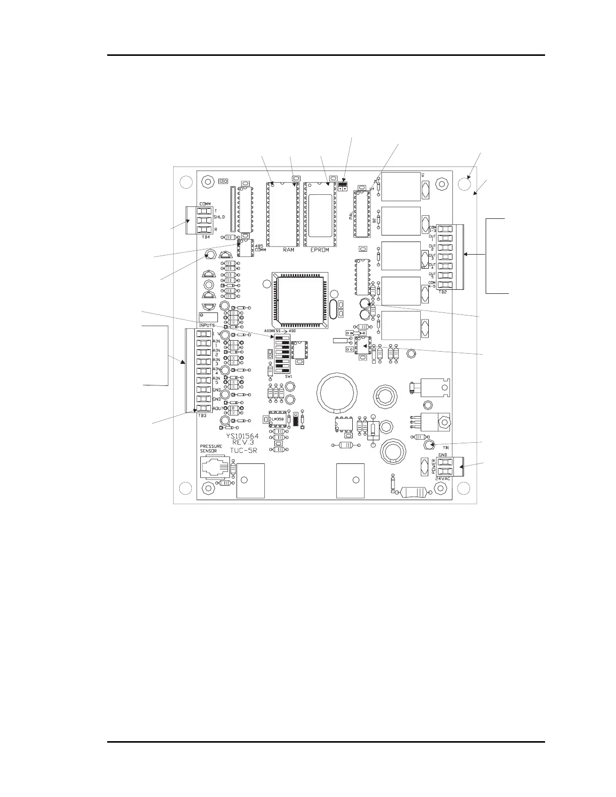
4.2 Becoming Familiar with the CV
Controller
HVAC Unit
Connections
Fan
Heat/Cool 1
Heat/Cool 2
Heat/Cool 3
Heat/Cool 4
Diagnostic Blink
Code LED
RS-485
Communications
Loop Connection
Typical
Pin 1
Indicator
RAM
Chip
EPROM
Chip
PAL
Chip
RAM Size
Select
Jumper
RS-485
Communications
Driver Chip
Real Time
Clock Chip
Mounting
Backplate
Mounting Hole
Typof4
Comm
LED
Address Switch
(Set Between
1 & 30)
Analog Inputs
Space Sensor
Slide Adjust
Supply Air Temp
Outdoor Air Temp
Auxiliary Alarm
Analog Output
0-10 VDC
Economizer
Power LED
24 VAC
Power Input
Figure 4-14: CV Controller Component Layout
4.2.1 24 VAC Power Connector
This connector provides power to the CV Controller.
24VAC - The “hot” side of the control transformer.
GND - The grounded side of the control transformer. If the secondary of the
control transformer is not grounded, you must still observe polarity if the
transformer powers any other device!