Section 4 Auto-Zone Plus
4-36 Start-Up and Troubleshooting
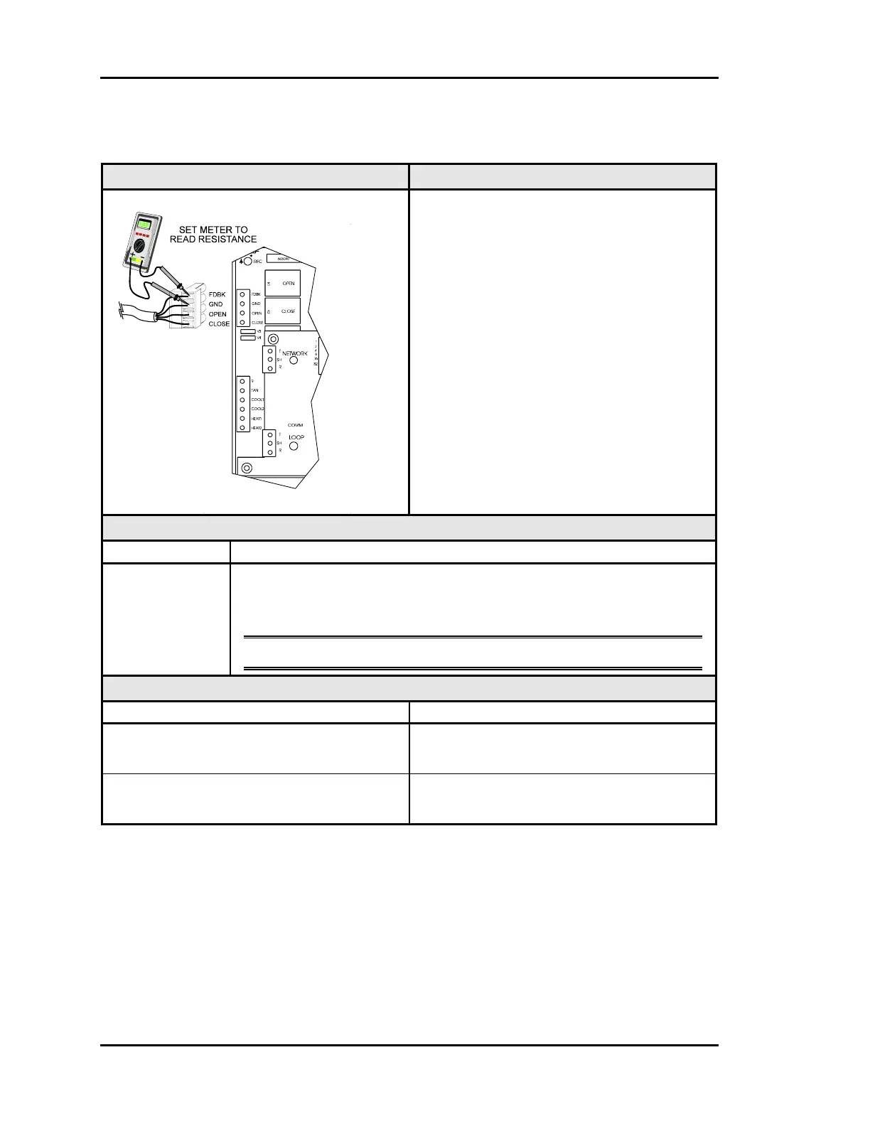
2.3.4 Zone Manager Bypass Damper Wiring Checks
Example Diagram Overvie
The Bypass Damper wiring can be checked
at the Zone Manager by unplugging the
Bypass Damper Connector and metering
the wiring.
All meter readings are taken with one
meter lead on the GND terminal of the
plug.
Feedback readings may vary considerably
due to physical travel limits on either the
damper or the actuator. The actuator should
be considered defective if the resistance at
it’s minimum position is 0 Ohms or is
greater than 10,000 Ohms at maximum
position.
See Bypass Actuator Troubleshooting for
additional details
Measurements
Meter Acceptable Range
FDBK - GND 0 Ohms @ Full CW position (typical 4 Ohms)
to
10,000 Ohms @ Full CCW position (typical 10,200 Ohms)
Note: Readings may vary due to physical travel limits.
Action
Condition Response
FDBK Resistance is 0 Ohms 1. Check for shorts or other wiring errors.
2. Replace Actuator.
FDBK Resistance is greater than 10,000
Ohms
1. Check for open circuit wiring errors.
2. Replace Actuator.