Auto-Zone Plus
Section 2
Design Guide 2-9
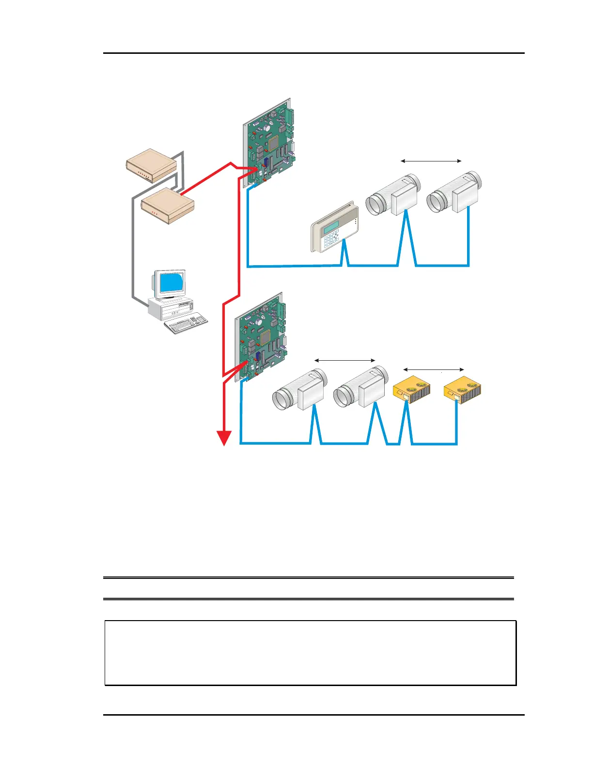
Figure 2-7: Communication Loop Wiring, Daisy-Chain Configuration
Even though the daisy chain configuration is preferred, the star configuration can also be
used. If required, a combination of the two can also be used. Remember, the best comm
loop wiring is the one which utilizes the minimum number of ends while using the
shortest wiring path.
Note: The loop does not have to follow the controller address sequence.
Caution: If comm loop is not installed in conduit be careful to position the cable
away from high noise devices like fluorescent lights, transformers,
VFD’s, etc. Conduit is not required for comm loop wiring unless
required by local codes.
CommLink II
(Set For Multiple Loop)
Computer
(Optional)
To Other Zone
Managers
(Up To 30 Per System)
Zone
Manager
#2
Zone
Manager
#1
RS-485
19200 Baud
RS-485
19200 Baud
RS-485
9600 Baud
RS-485
9600 Baud
WCLI
ATTMASTER ONTRO
S, NC
COMM LINK II
COMM
LINK
II
L
C
M
M
O
O
O
O
M
D
P
P
E
Constant Volume Units
Up to 13 CV Units May Be added To
Each Zone Manager Loop
System Manager
Local Loop
Local Loop
Network Loop
Network Loop
Zone Air Dampers
Zone Air Dampers
Up to 16 Zone Dampers Allowed
Up to 16 Zone Dampers Allowed
#1
#1
#18
#16
#16
#30
1
4
2
5
3
6
9
8
0
7
Enter
Esc
*
M
inus
Menu
Clear
Dec.
Alarm
Communication
Override
MANAGER
MANAGER
SYSTEM
SYSTEM
Auto-Z
one Plus
01/01/97 03:38PM
W
ED
OCCUPIED
NO
ALARMS
Sychronous Data Link
CONTROLS
SIG
DET
RDY
SND
REC
PWR
Remote Link
(Optional)