OPERATING INSTRUCTIONS
Model
2001
Depress the POWER push-button. The light in the switch
button should light, indicating an operating condition.
(Note: This instrument does not require a
warmup period
unless
it
is to be used at the extreme limits of its specifica-
tions.)
After completing the set-up, adjust the Model 2001 con-
trols for the required center frequency, sweep width, out-
put amplitude, and sweep rate. Turn the desired markers
on, and adjust their size and width.
3.5
SPECIAL OPERATING NOTES
3.5.1 Errors From Sweep Rate Effects
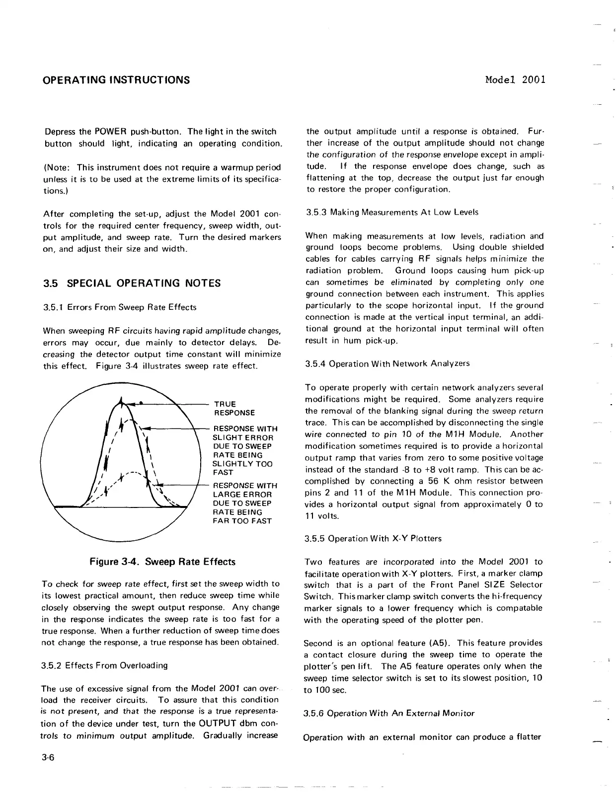
When sweeping RF circuits having rapid amplitude changes,
errors may occur, due mainly to detector delays. De-
creasing the detector output time constant will minimize
this effect.
Figure 3-4 illustrates sweep rate effect.
TRUE
RESPONSE
RESPONSE
WlTH
SLIGHT ERROR
DUE TO SWEEP
RATE
BEING
SLIGHTLY TOO
FAST
RESPONSE
WITH
LARGE ERROR
DUE TO SWEEP
RATE BEING
Figure
3-4.
Sweep Rate Effects
To check for sweep rate effect, first set the sweep width to
its lowest practical amount, then reduce sweep time while
closely observing the swept output response. Any change
in the response indicates the sweep rate is too fast for a
true response. When a further reduction of sweep time does
not change the response, a true response has been obtained.
3.5.2 Effects From Overloading
The use of excessive signal from the Model 2001 can over-
load the receiver circuits. To assure that this condition
is
not present, and that the response is a true representa-
tion of the device under test, turn the OUTPUT dbm con-
trols to minimum output amplitude. Gradually increase
the output amplitude until a response is obtained.
Fur-
ther increase of the output amplitude should not change
the configuration of the response envelope except in ampli-
tude. If the response envelope does change, such as
flattening at the top, decrease the output just far enough
to restore the proper configuration.
3.5.3 Making Measurements At Low Levels
When making measurements at low levels, radiation and
ground loops become problems. Using double shielded
cables for cables carrying RF signals helps minimize the
radiation problem. Ground loops causing hum pick-up
can sometimes be eliminated by completing only one
ground connection between each instrument. This applies
particularly to the scope horizontal input. If the ground
connection is made at the vertical input terminal, an addi-
tional ground at the horizontal input terminal will often
result in hum pick-up.
3.5.4 Operation With Network Analyzers
To operate properly with certain network analyzers several
modifications might be required. Some analyzers require
the removal of the blanking signal during the sweep return
trace. This can be accomplished by disconnecting the single
wire connected to pin 10 of the
M1H Module. Another
modification sometimes required is to provide a horizontal
output ramp that varies from zero to some positive voltage
instead of the standard
-8
to
+8
volt ramp. This can be ac-
complished by connecting a 56
K
ohm resistor between
pins 2 and 11 of the
M1H
Module. This connection pro-
vides a horizontal output signal from approximately
0 to
11 volts.
3.5.5 Operation With
X-Y
Plotters
Two features are incorporated into the Model 2001 to
facilitate operation with
X-Y
plotters. First,
a
marker clamp
switch
that is a part of the Front Panel
SIZE Selector
Switch. This marker clamp switch converts the hi-frequency
marker signals to a lower frequency which is compatable
with the operating speed of the plotter pen.
Second is an optional feature
(A5). This feature provides
a contact closure during the sweep time to operate the
plotter's pen lift. The A5 feature operates only when the
sweep time selector switch is set to its slowest position, 10
to
100 sec.
3.5.6 Operation With An External Monitor
Operation with an external monitor can produce a flatter
OPERATING INSTRUCTIONS
Depress
the
POWER
push-button.
The
light in
the
switch
button
should light, indicating an
operating
condition.
(Note:
This
instrument
does
not
require
a
warmup
period
unless
it
is
to
be used
at
the
extreme
limits
of
its specifica-
tions.)
After
completing
the
set-up,
adjust
the
Model 2001 con-
trols
for
the
required
center
frequency,
sweep
width,
out·
put
amplitude,
and sweep rate.
Turn
the
desired
markers
on,
and
adjust
their
size and
width.
3.5 SPECIAL OPERATING NOTES
3.5.1 Errors
From
Sweep
Rate
Effects
When sweeping RF
circuits
having rapid
amplitude
changes,
errors
may
occur,
due
mainly
to
detector
delays.
De-
creasing
the
detector
output
time
constant
will minimize
this
effect.
Figure 3-4 illustrates sweep rate
effect.
TRUE
RESPONSE
........
1-------'.....-- RESPONSE
WITH
SLIGHT
ERROR
DUE
TO
SWEEP
RATE
BEING
SLiGHTL
Y
TOO
FAST
.......
~----/'--
RESPONSE
WITH
LARGE
ERROR
DUE
TO
SWEEP
RATE
BEING
FAR
TOO
FAST
Figure 3-4. Sweep Rate Effects
To
check for
sweep
rate
effect,
first
set
the
sweep
width
to
its lowest practical
amount,
then
reduce
sweep
time
while
closely observing
the
swept
output
response.
Any
change
in
the
response indicates
the
sweep rate
is
too
fast
for
a
true
response. When a
further
reduction
of
sweep
time
does
not
change
the
response, a
true
response has
been
obtained.
3.5.2
Effects
From
Overloading
The
use
of
excessive signal from
the
Model
2001
can over-
load
the
receiver circuits.
To
assure
that
this
condition
is
not
present,
and
that
the
response
is
a
true
representa-
tion
of
the
device
under
test,
turn
the
OUTPUT
dbm
con-
trols
to
minimum
output
amplitude.
Gradually increase
3-6
Model 2001
the
output
amplitude
until a response
is
obtained.
Fur-
ther
increase
of
the
output
amplitude
should
not
change
the
configuration
of
the
response envelope
except
in
ampli-
tude.
If
the
response envelope
does
change, such as
flattening
at
the
top,
decrease
the
output
just
far enough
to
restore
the
proper
configuration.
3.5.3
Making Measurements
At
Low Levels
When making
measurements
at
low levels, radiation and
ground
loops
become
problems. Using
double
shielded
cables
for
cables carrying RF signals helps
minimize
the
radiation
problem.
Ground
loops causing
hum
pick-up
can
sometimes
be
eliminated
by
completing
only
one
ground
connection
between
each
instrument.
This applies
particularly
to
the
scope
horizontal
input. I f
the
ground
connection
is
made
at
the
vertical
input
terminal,
an addi-
tional
ground
at
the
horizontal
input
term
ina I will
often
result
in
hum
pick-up.
3.5.4
Operation
With
Network
Analyzers
To
operate
properly
with
certain
network
analyzers
several
modifications
might
be required.
Some
analyzers require
the
removal
of
the
blanking signal
during
the
sweep
return
trace.
This
can
be
accomplished
by
disconnecting
the
single
wire
connected
to
pin
10
of
the
M 1 H Module.
Another
modification
sometimes
required
is
to
provide a horizontal
output
ramp
that
varies from zero
to
some
positive voltage
instead
of
the
standard
·8
to
+8
volt
ramp. Th
is
can be ac·
complished by
connecting
a
56
K
ohm
resistor
between
pins 2
and
11
of
the
M 1 H Module. Th
is
connection
pro-
vides a
horizontal
output
signal from
approximately
0
to
11
volts.
3.5.5
Operation
With
X-
Y
Plotters
Two
features are
incorporated
into
the Model 2001
to
facil
itate
operation
with
X-
Y
plotters.
First, a
marker
clamp
switch
that
is a
part
of
the
Front
Panel
SI
ZE
Selector
Switch.
This
marker
clamp
switch
converts
the
hi-frequency
marker
signals
to
a lower
frequency
which
is
compatable
with
the
operating
speed
of
the
plotter
pen.
Second
is
an
optional
feature
(A5). This featu
re
provides
a
contact
closure
during
the
sweep
time
to
operate
the
plotter's
pen lift.
The
A5
feature
operates
only
when
the
sweep
time
selector
switch
is
set
to
its slowest position,
10
to
100
sec.
3.5.6
Operation
With
An
External
Monitor
Operation
with
an
external
monitor
can
produce
a
flatter
 Loading...


