OPERATING INSTRUCTIONS
Model
2001
@
TRIGIRECUR Switch
-
@
SWEEP
TIME
Sec.
VARIMANUAL
Control
-
Selects recurring sweep of the time selected by SWEEP TlME Control when
in RECUR (down) position and with MODE Switch in either
S/S or nF. When
TRIG/RECUR Switch
is
in the center position, the sweep may be triggered for
single sweep operation by momentarily contacting the
TRIG (up) position
This
is
a six positionSwitch/Control. The outer knob provides selection of MAN-
UAL,
LlNE or Four Decade Ranges of variable sweep time. The inner knob pro-
vides manual frequency sweeping when SWEEP
TlME Sec. Switch
is
set to
MANUAL, and variable adjustment of sweep time in each of the four decade
ranges. (The sweep may be triggered in the four decade ranges only).
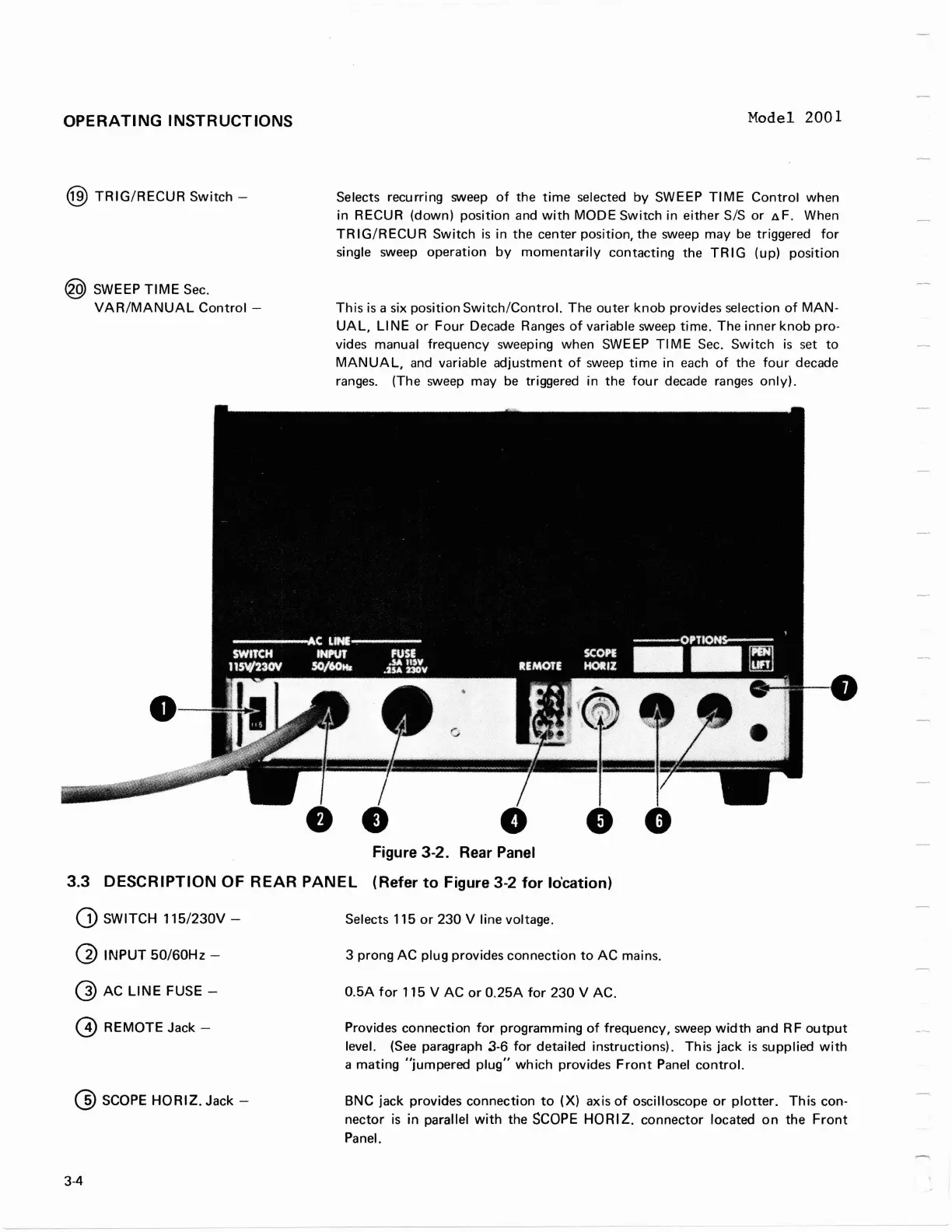
Figure 3-2. Rear Panel
3.3
DESCRIPTION OF REAR PANEL (Refer to Figure 3-2 for Io'cation)
SWITCH 115/230V
-
Selects 115 or 230 V line voltage.
@
INPUT 50160Hz
-
3 prong AC plug provides connection to AC mains.
@
AC
LINE FUSE
-
0.5A for 115 V AC or 0.25A for 230 V AC.
@
REMOTE Jack
-
Provides connection for programming of frequency, sweep width and RF output
level.
(See paragraph 3-6 for detailed instructions). This jack
is
supplied with
a mating
"jumpered plug" which provides Front Panel control.
@
SCOPE HORIZ. Jack
-
BNC
jack provides connection to
(X)
axis of oscilloscope or plotter. This con-
nector
is
in parallel with the
SCOPE
HORIZ.
connector located on the Front
Panel.
OPERATING
INSTRUCTIONS
@)
TRIG/RECUR
Switch
-
@ SWEEP
TIME
Sec.
VAR/MANUAL
Control
-
Model 2001
Selects recurring sweep
of
the
time
selected
by
SWEEP
TIME
Control
when
in RECUR (down) position and
with
MODE
Switch
in
either
SIS
or
~F.
When
TR
I
G/R
ECU R
Switch
is
in
the
center position, the sweep may
be
triggered
for
single sweep operation
by
momentarily
contacting the
TR
IG (up) position
This
is
a six position
Switch/Control.
The
outer
knob
provides selection
of
MAN-
UAL,
LINE
or
Four
Decade Ranges
of
variable sweep time. The
inner
knob
pro-
vides manual frequency sweeping when SWEEP
TI
ME Sec.
Switch
is
set
to
MANUAL,
and variable adjustment
of
sweep
time
in each
of
the
four
decade
ranges. (The sweep may
be
triggered in
the
four
decade ranges
only).
•
Figure 3-2. Rear Panel
3.3 DESCRIPTION OF
REAR
PANEL
(Refer
to
Figure 3-2
for
lo'cation)
CD
SWITCH
115/230V-
@
INPUT
50/60Hz-
Q)
AC
LINE
FUSE -
@ REMOTE Jack -
@ SCOPE
HORIZ.
Jack -
3-4
Selects 115
or
230
V line voltage.
3 prong
AC
plug provides connection
to
AC
mains.
0.5A
for
115 V
AC
or
O.25A
for
230
V AC.
Provides connection
for
programming
of
frequency, sweep
width
and R F
output
level.
(See
paragraph 3-6
for
detailed instructions). This
jack
is
supplied
with
a
mating
"jumpered
plug"
which
provides
Front
Panel
control.
BNC jack provides connection
to
(X) axis
of
oscilloscope
or
plotter.
This
con-
nector
is
in
parallel
with
the
SCOPE
HORI
Z.
connector
located
on
the
Front
Panel.