Model
2001
SECTION
5
5.1
INTRODUCTION
This section provides information for testing, calibrating,
and trouble shooting the sweep generator. The performance
test
is
designed for incoming inspection and periodic evalua-
tion. If performance is not to specifications, refer to the
calibration and trouble shooting sections.
5.2
SERVICE INFORMATION
5.2.1
DISASSEMBLY INFORMATION
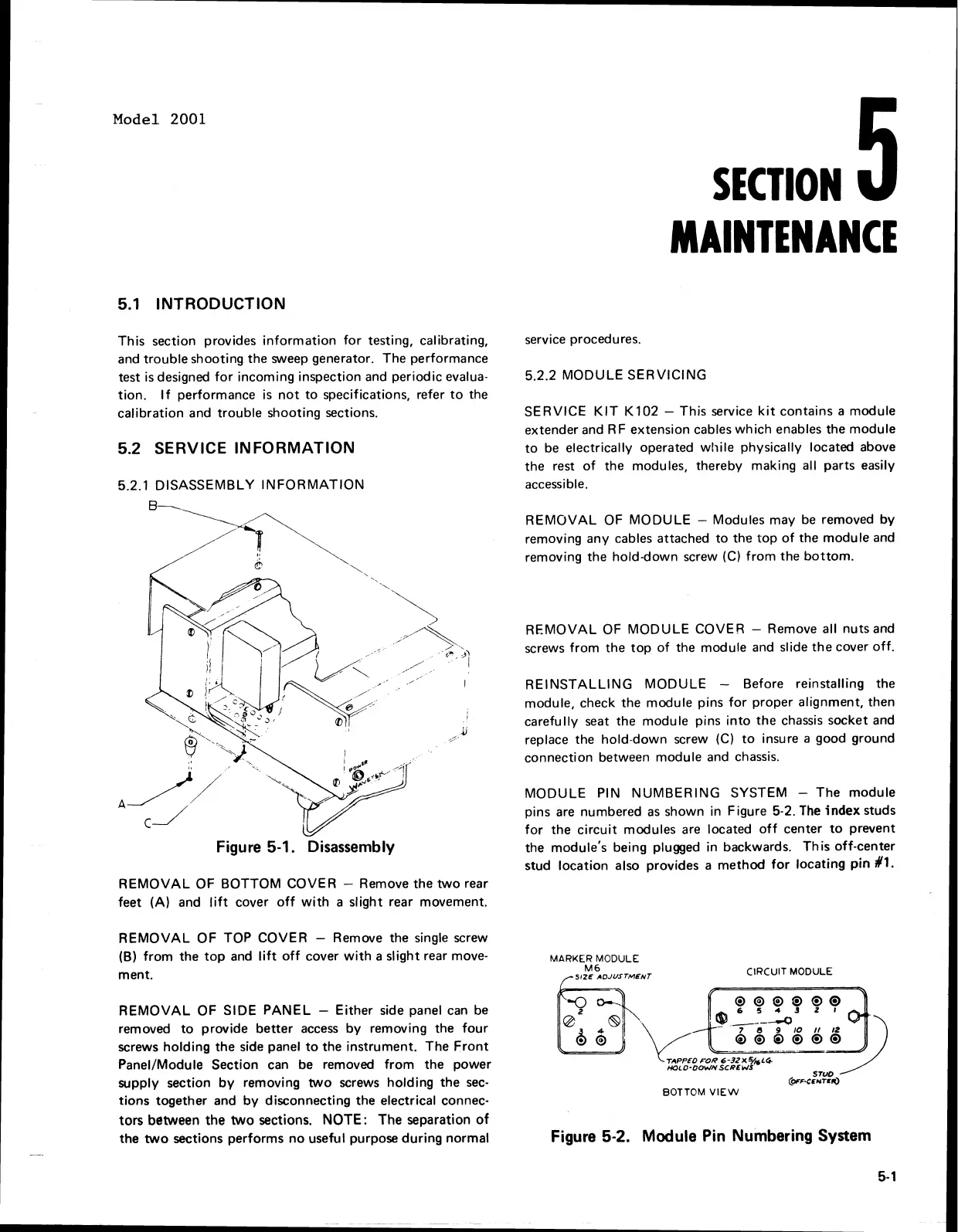
Figure
5-1.
Disassembly
REMOVAL OF BOTTOM COVER
-
Remove the two rear
feet (A) and lift cover off with a slight rear movement.
REMOVAL OF TOP COVER
-
Remove the single screw
(6)
from the top and lift off cover with a slight rear move-
ment.
REMOVAL OF
SIDE PANEL
-
Either side panel can be
removed to provide better access by removing the four
screws holding the side panel to the instrument. The Front
Panel/Module Section can be removed from the power
supply section by removing two screws holding the sec-
tions together and by disconnecting the electrical connec-
tors between the two sections.
NOTE:
The separation of
the two sections performs no useful purpose during normal
service procedures.
5.2.2
MODULE SERVICING
SERVICE KIT
K
102
-
This service kit contains a module
extender and
RF extension cables which enables the module
to be electrically operated while physically located above
the rest of the modules, thereby making all parts easily
accessible.
REMOVAL OF MODULE
-
Modules may be removed by
removing any cables attached to the top of the module and
removing the hold-down screw
(C)
from the bottom.
REMOVAL OF MODULE COVER
-
Remove all nuts and
screws from the top of the module and slide the cover off.
REINSTALLING MODULE
-
Before reinstalling the
module, check the module pins for proper alignment, then
carefully seat the module pins into the chassis socket and
replace the hold-down screw
(C)
to insure
a
good ground
connection between module and chassis.
MODULE PIN NUMBERING SYSTEM
-
The module
pins are numbered as shown in Figure
5-2.
The
index
studs
for the circuit modules are located off center to prevent
the module's being plugged in backwards. This off-center
stud location also provides a method for locating
pin
$1.
MARKER
MODULE
M6
S~ZE
ADJUSTMENT
CIRCUIT
MODULE
E.;.
TlPPKOroR 6-3ZXVfiLCF
HOLD-OO*/NSCRbWS
BOTTOM
VIEW
Figure
5-2.
Module Pin Numbering System
5-
1
Model 2001
5.1
INTRODUCTION
This
section provides
information
for
testing, calibrating,
and
trouble
shooting the sweep generator. The performance
test is designed
for
incoming inspection and periodic evalua-
tion.
If
performance is
not
to
specifications, refer
to
the
calibration and
trouble
shooting sections.
5.2 SERVICE INFORMATION
5.2.1
DISASSEMBLY
INFORMATION
REMOVAL
OF
BOTTOM
COVER - Remove the
two
rear
feet (A) and
lift
cover
off
with
a slight rear movement.
REMOVAL
OF
TOP COVER - Remove the single screw
(B)
from
the
top
and
lift
off
cover
with
a slight rear move-
ment.
REMOVAL
OF
SIDE
PANEL
-
Either
side panel
can
be
removed
to
provide
better
access
by
removing the
four
screws
holding
the
side panel
to
the instrument. The
Front
Panel/Module Section can be removed
from
the
power
supply section
by
removing
two
screws
holding
the
sec-
tions
together and
by
disconnecting the electrical connec·
tors
between
the
two
sections.
NOTE:
The separation
of
the
two
sections performs
no
useful purpose
during
normal
service procedures.
SECTION
MAINTENANCE
5.2.2
MODULE
SERVICING
SERVICE
KIT
K102
- This service
kit
contains a module
extender and RF extension cables
which
enables the module
to
be
electrically operated
while
physically located above
the rest
of
the modules, thereby making all parts easily
accessible.
REMOVAL
OF
MODULE
- Modules may
be
removed
by
removing any cables attached
to
the
top
of
the
module
and
removing the hold-down screw (C)
from
the
bottom.
REMOVAL
OF
MODULE
COVER - Remove all nuts and
screws
from
the
top
of
the module and slide
the
cover
off.
REINSTALLING
MODULE
- Before reinstalling the
module, check the module pins
for
proper alignment, then
carefully seat the module pins
into
the
chassis socket and
replace the hold-down screw (C)
to
insure a good ground
connection between module and chassis.
MODULE
PIN
NUMBERING
SYSTEM -
The
module
pins
are
numbered
as
shown in Figure 5-2.
The
index studs
for
the
circuit
modules
are
located
off
center
to
prevent
the module's being plugged in backwards.
This
off-center
stud location also provides a
method
for
locating
pin
11.
MARKER MODULE
M6
SIZE
ADJUSTMENT
CIRCUIT MODULE
BOTTOM
VIEW
Figure 5·2. Module Pin Numbering System
5·'