Model
2001
OPERATING INSTRUCTIONS
(less amplitude variation) input signal to the device under
test than is obtainable with the internal monitor, since the
monitor point is located at the point where greatest flatness
is desired, and
is not affected by cable VSWR or input
impedance of the device under test. Another application
is to level at the output point of a wide band power ampli-
fier, in order to increase the output power capability of
the sweep generator.
To operate with an external monitor, first set the OUTPUT
controls for maximum, +10
dBm. Next, connect the out-
put from the external monitor to the Front Panel BNC
jack labeled ALC IN and set the ALC
EXTIINT Switch
to the EXT position. The signal from the external monitor
must be of a negative polarity between 0.2 and
2
volts. If
the signal is larger than
2
volts, use a resistive divider
to obtain the less than
2
volts signal. While observing the
output from the monitor on an oscilloscope, adjust the
Vernier OUTPUT Control until the monitor signal becomes
leveled. (Refer to Figure 3-5.)
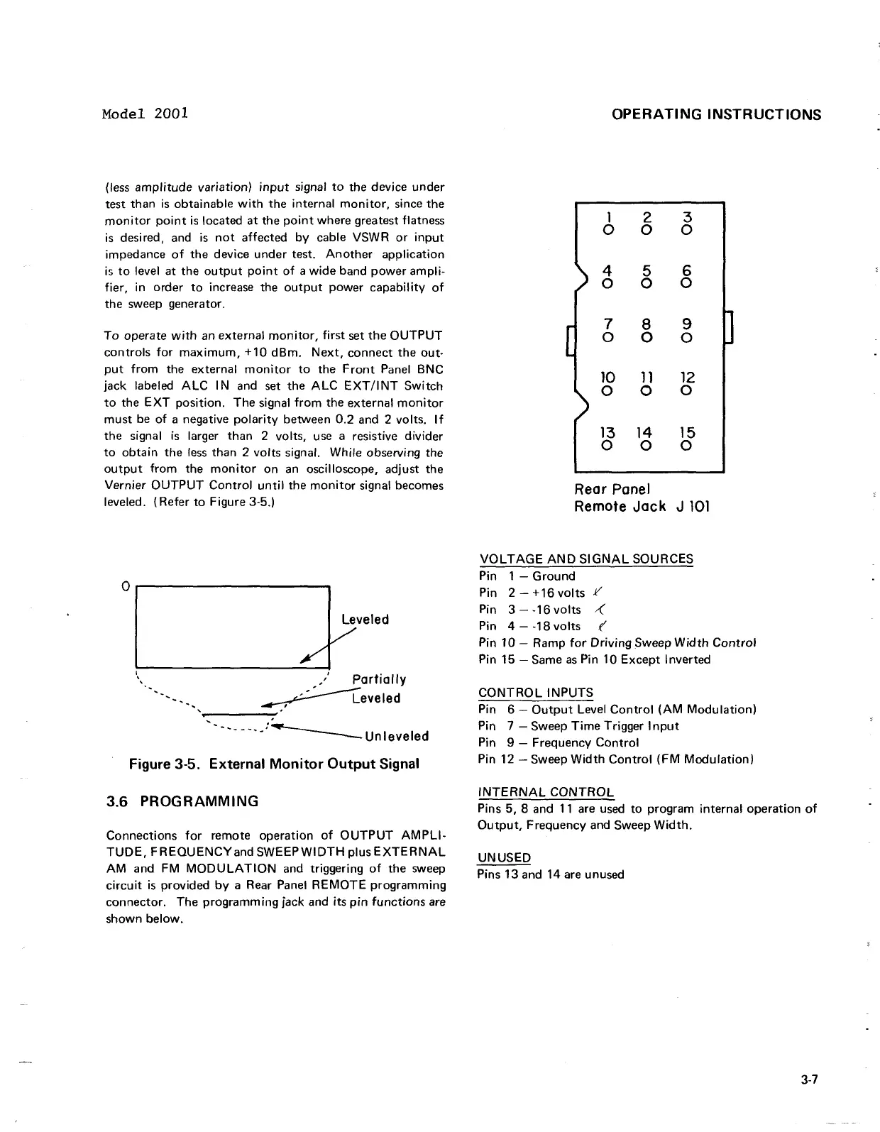
Rear
Panel
Remote Jack J
101
VOLTAGE AND SIGNAL SOURCES
Pin
1
-
Ground
Pin 2
-
+16 volts
.I/
I
Pin 3
-
-16 volts
.(
Pin
4
-
-18 volts
f'
Pin 10
-
Ramp for Driving Sweep Width Control
Pin 15
-
Same as Pin 10 Except Inverted
I.
:
Partiallv
CONTROL INPUTS
Pin 6
-
Output Level Control (AM Modulation)
.--
.---.A:\
Unleveled
Pin
7
-
Sweep Time Trigger Input
Pin
9
-
Frequency Control
Figure
3-5.
External Monitor Output Signal
Pin 12 -Sweep Width Control (FM Modulation)
3.6
PROGRAMMING
INTERNAL CONTROL
Pins 5, 8 and 11 are used to program internal operation of
Output, Frequency and Sweep Width.
Connections for remote operation of OUTPUT AMPLI-
TUDE, FREQUENCY and SWEEP WIDTH
PIUS EXTERNAL
UNUSED
AM and FM MODULATION and triggering of the sweep
Pins
13and
14
are
unused
circuit is provided by a Rear Panel REMOTE programming
connector. The programming jack and its pin functions are
shown below.
Model 2001
(less
amplitude
variation)
input
signal
to
the device
under
test than
is
obtainable
with
the internal
monitor,
since the
monitor
point
is
located
at
the
point
where greatest flatness
is
desired, and
is
not
affected
by
cable VSWR
or
input
impedance
of
the device
under
test.
Another
application
is
to
level at the
output
point
of
a
wide
band
power
ampli-
fier, in order
to
increase the
output
power
capability
of
the sweep generator.
To
operate
with
an external
monitor,
first
set
the
OUTPUT
controls
for
maximum,
+10
dBm.
Next,
connect the out-
put
from
the external
monitor
to
the
Front
Panel BNC
jack labeled
ALC
I N and set the
ALC
EXT/I
NT
Switch
to
the
EXT
pOSition. The signal
from
the external
monitor
must
be
of
a negative
polarity
between 0.2 and 2 volts.
If
the signal
is
larger than 2 volts, use a resistive divider
to
obtain the
less
than 2 volts signal. While observing the
output
from
the
monitor
on
an
oscilloscope, adjust the
Vernier
OUTPUT
Control
until
the
monitor
signal becomes
leveled. (Refer
to
Figure 3-5.)
°1
______
#f,eled
\
,/
Partially
-,
~eveled
-----:'
'------'-:~unleveled
Figure 3-5. External
Monitor
Output
Signal
3.6
PROGRAMMING
Connections
for
remote operation
of
OUTPUT
AMPLI-
TUDE,
FREQUENCYand
SWEEP
WIDTH
plus
EXTERNAL
AM
and FM
MODULATION
and triggering
of
the sweep
circuit
is
provided
by
a Rear Panel
REMOTE
programming
connector. The
programming
jack and its
pin
functions
are
shown below.
OPERATING
INSTRUCTIONS
1 2 3
0 0 0
4 5
6
0 0
0
7
8
9
0
0
0
10
11
12
0 0
0
13 14 15
0
0 0
Rear Panel
Remote
Jack
J
101
VOLTAGE
AND
SIGNAL
SOURCES
Pin 1 -
Ground
Pin 2 -
+16
volts
Y
Pin 3 - -16
volts
~
Pin 4 - -18
volts
(
Pin 10 - Ramp
for
Driving
Sweep
Width
Control
Pin 15 - Same
as
Pin 10
Except
Inverted
CONTROL
INPUTS
Pin 6 -
Output
Level
Control
(AM
Modulation)
Pin 7 - Sweep
Time
Trigger
Input
Pin 9 - Frequency
Control
Pin 12 - Sweep
Width
Control
(FM
Modulation)
INTERNAL
CONTROL
Pins 5, 8 and
11
are used
to
program internal operation
of
Output,
Frequency and Sweep
Width.
UNUSED
Pins 13 and 14 are unused
3-7