OPERATING INSTRUCTIONS
Model
2001
3.6.1 OUTPUT AMPLITUDE CONTROL
(AM MODULATION)
Normal internal control is provided by a jumper wire con-
nected
between pins
5
and 6 of the REMOTE plug as
shown below.
REMOTE PLUG
TO RF OUTPUT AMPLITUDE
-q
I
I
CONTROL CIRCUIT
FRONT PANEL
VERNIER OUTPUT
CONTROL
(0 to 20dB)
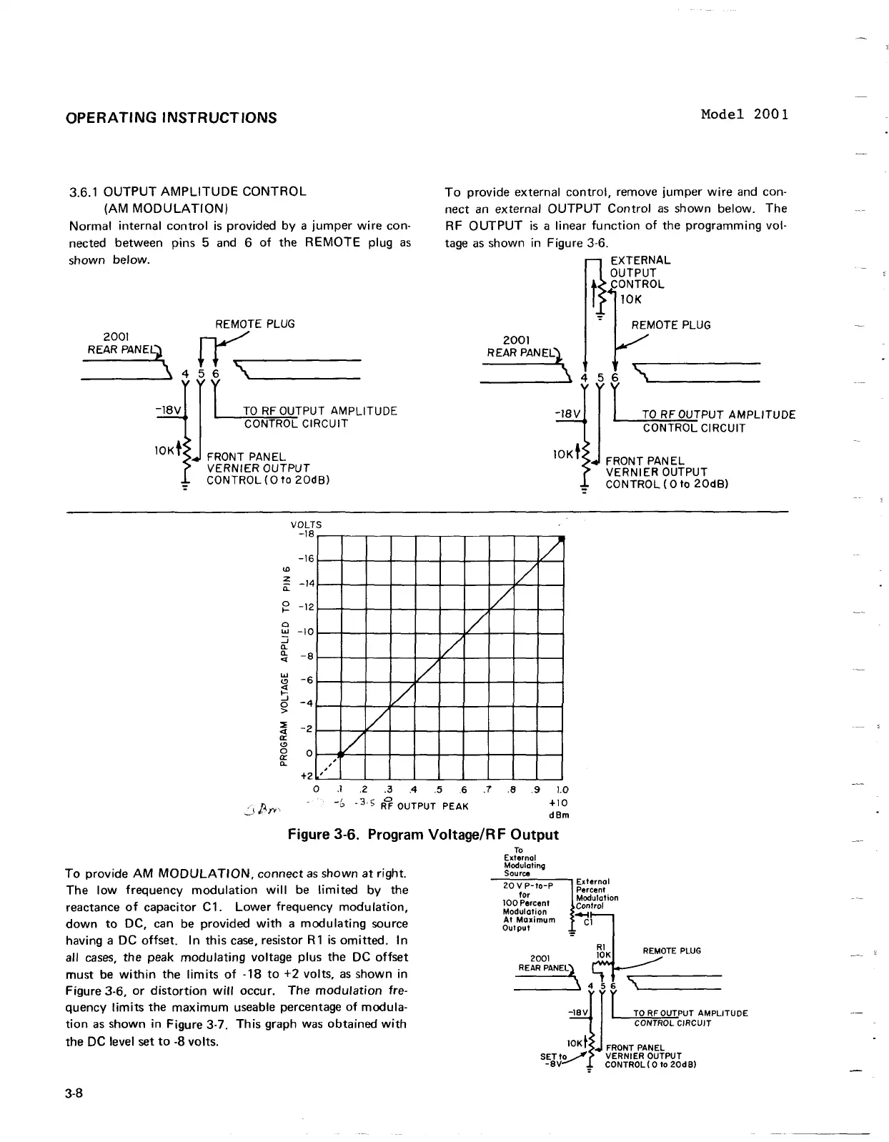
To provide external control, remove jumper wire and con-
nect an external OUTPUT Control as shown below. The
RF OUTPUT is a linear function of the programming vol-
tage as shown in Figure
3-6.
EXTERNAL
REMOTE PLUG
YE
456
YYY
-4
I
1
TORFOUTPUT AMPLITUDE
CONTROL CIRCUIT
FRONT PANEL
VERNIER OUTPUT
CONTROL (0 to 20dB)
-
VOLTS
012345678910
-5
-3
R?
OUTPUT
PEAK
+I0
J
C"P
dBm
Figure
3-6.
Program VoltageIR
F
Output
TO
External
Modulatinq
To provide AM MODULATION, connect as shown at right.
Sourw
The low frequency modulation will be limited by the
reactance of capacitor
C1. Lower frequency modulation,
Modulation
down to DC, can be provided with
a
modulating source
At
Moximurn
output
having a DC offset.
In this case, resistor
R1 is omitted. In
all cases, the peak modulating voltage plus the DC offset
must be within the limits of
-18
to
+2
volts, as shown in
Figure
3-6, or distortion will occur. The modulation fre-
quency limits the maximum useable percentage of modula-
tion as shown in Figure 3-7. This graph was obtained with
the
DC
level set to
-8
volts.
OPERATING
INSTRUCTIONS
3.6.1
OUTPUT
AMPLITUDE
CONTROL
(AM
MODULATION)
Normal
internal
control
is
provided
by
a
jumper
wire
con-
nected between pins
5
and
6
of
the
REMOTE
plug
as
shown below.
REMOTE
PLUG
2001
~
REAR
PANEL)
~
~
"'C"""
____
\~
4 5 6
\------
-18V
J I
TO
RF
OUTPUT AMPLITUDE
CONTROL CIRCUIT
10Kt
FRONT
PANEL
VERNIER OUTPUT
CONTROL
(0
to
20dB)
VOLTS
-18
-16
Ul
z
-14
a::
0
-12
l-
e
w
-10
:J
a..
a..
-8
<f
1/
w
-6
Cl
<f
~
-4
0
V
/.-
,
,
>
~
-2
<f
a::
Cl
0
0
cr
a..
,
+2
,
V
Model
2001
To
provide external
control,
remove
jumper
wire
and con-
nect
an
external
OUTPUT
Control
as
shown below. The
RF
OUTPUT
is
a linear
function
of
the programming vol-
tage
as
shown in Figure 3-6.
'/
i/
EXTERNAL
OUTPUT
t CONTROL
-:-
RO:EMOTE
PLUG
2001
REAR
PANEL)'
\ 4 5 6
"\
.....
____
_
V
~
-18V
J I
TO
RF OUTPUT AMPLITUDE
CONTROL CIRCUIT
10Kt
FRONT PANEL
/
VERNIER OUTPUT
CONTROL
(0
to
20dB)
o
.1
.2
.3
.4 .5 .6 .7
.8
.9
1.0
-(,
-3·5
R~
OUTPUT PEAK
+10
dBm
Figure 3-6. Program Voltage/R F
Output
To
provide
AM
MODULATION,
connect
as
shown
at
right.
The
low
frequency
modulation
will
be
limited
by the
reactance
of
capacitor C1.
Lower
frequency
modulation,
down
to
DC, can
be
provided
with
a
modulating
source
having a DC offset.
In
this
case,
resistor
R1
is
omitted.
In
all
cases,
the peak
modulating
voltage plus the DC
offset
must
be
within
the
limits
of
-18
to
+2 volts,
as
shown in
Figure 3-6,
or
distortion
will
occur. The
modulation
fre-
quency
limits
the
maximum
useable percentage
of
modula-
tion
as
shown in Figure 3-7. This graph was obtained
with
the DC level set
to
-8 volts.
3-8
To
External
Modulating
Source
--:2:C:0~V:':P::"--:-to--=-P
----,
Ex
terna I
for
~~C:I~~ion
100
Percent Control
Modulation
4-l
At
Maximum
Cl
Output
2001
REAR
PANEL)
REMOTE
PLUG
____
..... , 4
56
;"jJ
r
TO
RFOUTPUT AMPLITUDE
CONTROL CIRCUIT
10K
t FRONT PANEL
SETty
VERNIER OUTPUT
-8V
; CONTROL( 0 to
20dB)