Model
200
1
OPERATING INSTRUCTIONS
@
OPTIONS
-
0
PEN LIFT OPTION (A-5)
-
Provides mounting holes for BNC connectors used with special modifications or
options.
When Pen Lift Option is installed, these
2
terminals provide contact closure during
sweep "ON" time. This option operates only when the Front Panel SWEEP
TIME Selector is set to the 100-10 SEC. position.
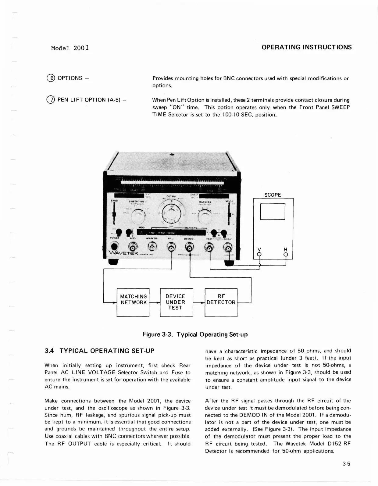
Figure
3-3.
Typical Operating Set-up
3.4
TYPICAL OPERATING SET-UP
have a characteristic impedance of 50 ohms, and should
be kept as short as practical (under
3
feet). If the input
When initially setting up instrument, first check Rear
impedance of the device under test is not 50-ohms, a
Panel AC
LINE VOLTAGE Selector Switch and Fuse to
matching network, as shown in Figure
3-3,
should be used
ensure the instrument is set for operation with the available
to ensure a constant amplitude input signal to the device
AC mains. under test.
-
Make connections between the Model 2001, the device
under test, and the oscilloscope as shown in Figure
3-3.
Since hum, RF leakage, and spurious signal pick-up must
be kept to a minimum,
it
is essential that good connections
and grounds be maintained throughout the entire setup.
Use
coaxial
cables
with
BNC
connectors wherever possible.
The RF OUTPUT cable is especially critical.
It
should
R
F
DETECTOR
After the RF signal passes through the RF circuit of the
device under test
it
must be demodulated before being con-
nected to the DEMOD
IN of the Model 2001. If a demodu-
lator is not a part of the device under test, one must be
added externally. (See Figure
3-3).
The input impedance
of the demodulator must present the proper load to the
RF circuit being tested. The Wavetek Model
Dl52 RF
Detector is recommended for 50-ohm applications.
-
DEVICE
UNDER
TEST
-
MATCH l
NG
NETWORK
-
Model
2001
OPERATING INSTRUCTIONS
@
OPTIONS
-
Provides
mounting
holes
for
BNC
connectors
used
with
special
modifications
or
options.
(j) PEN
LI
FT
OPTION
(A-5)
-
When
Pen
Lift
Option
is
installed, these 2
terminals
provide
contact
closure
during
sweep
"ON"
time.
This
option
operates
only
when
the
Front
Panel SWEEP
TIME
Selector
is
set
to
the
100-10 SEC.
position.
MATCHING
NETWORK
DEVICE
UNDER
TEST
RF
DETECTOR
SCOPE
D
Figure 3-3.
Typical
Operating
Set-up
3.4
TYPICAL
OPERATING SET-UP
When
initially
setting
up
instrument,
first
check Rear
Panel
AC
LINE
VOLTAGE
Selector
Switch
and Fuse
to
ensure
the
instrument
is set
for
operation
with
the
available
AC
mains.
Make
connections
between the
Model
2001,
the
device
under
test, and
the
oscilloscope
as
shown
in Figure 3-3.
Since
hum,
R F leakage, and spurious signal
pick-up
must
be
kept
to
a
minimum,
it
is essential
that
good
connections
and
grounds
be
maintained
throughout
the
entire
setup.
Use
coaxial cables
with
BNC
connectors
wherever
possible.
The
RF
OUTPUT
cable is especially
critical.
It
should
have a
characteristic
impedance
of
50
ohms, and
should
be
kept
as
short
as
practical
(under
3
feet).
If
the
input
impedance
of
the
device
under
test
is
not
50-ohms, a
matching
network,
as
shown
in
Figure
3-3, should be used
to
ensure a
constant
amplitude
input
signal
to
the
device
under
test.
After
the R F signal
passes
through
the
R F
circu
it
of
the
device
under
test
it
must
be
demodulated
before
being
con-
nected
to
the
DEMOD
IN
of
the
Model
2001.
If
a
demodu-
lator
is
not
a
part
of
the
device
under
test,
one
must
be
added
externally.
(See
Figure
3-3).
The
input
impedance
of
the
demodulator
must
present
the
proper
load
to
the
RF
circuit
being tested.
The
Wavetek
Model
0152
RF
Detector
is
recommended
for
50·ohm
applications.
3-5