OPERATING INSTRUCTIONS
Model
2001
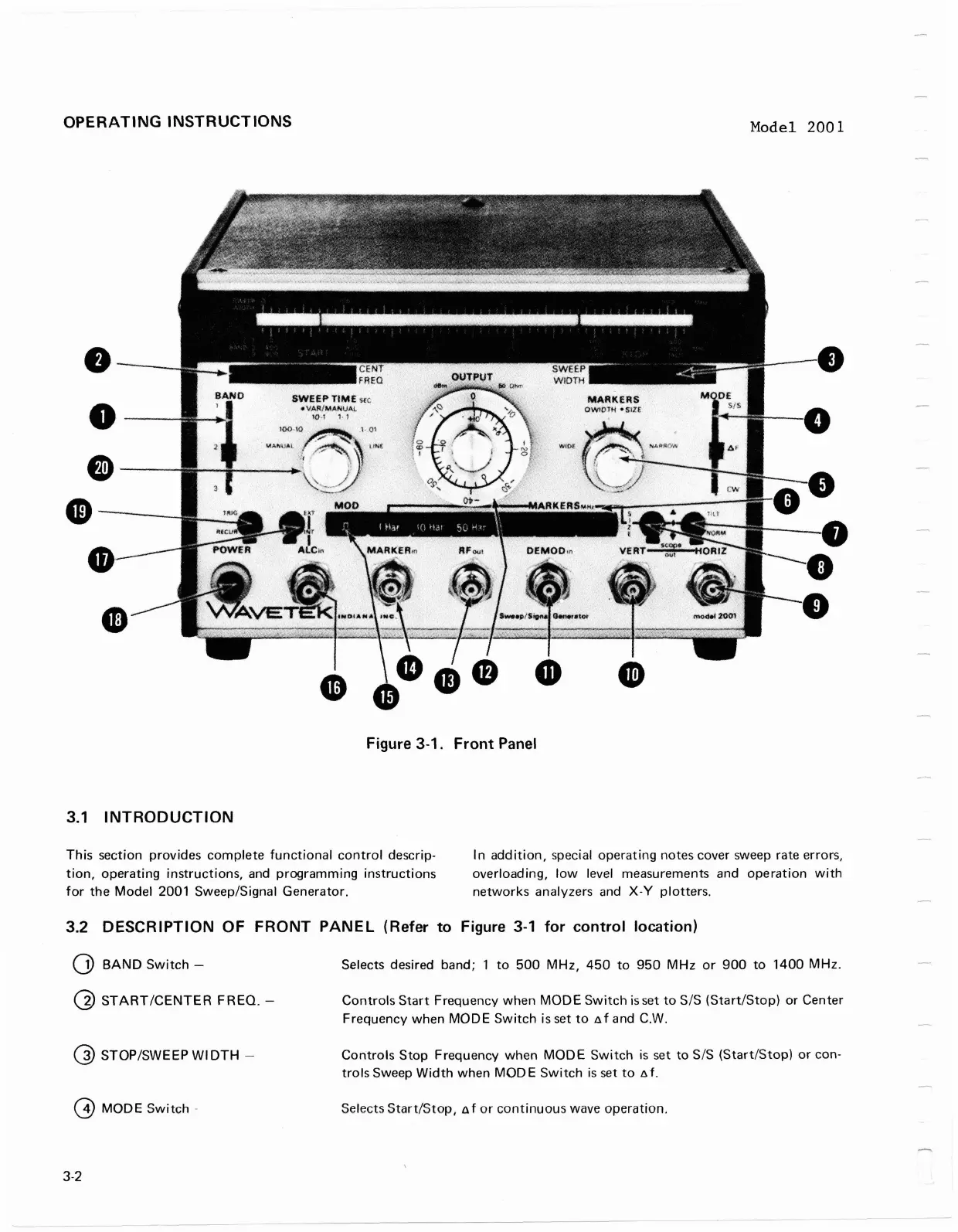
Figure 3-1. Front Panel
3.1
INTRODUCTION
This section provides complete functional control descrip-
In addition, special operating notes cover sweep rate errors,
tion, operating instructions, and programming instructions
overloading, low level measurements and operation with
for the Model 2001
Sweep/Signal Generator.
networks analyzers and
X-Y
plotters.
3.2
DESCRIPTION OF FRONT PANEL (Refer to Figure 3-1 for control location)
0
BAND Switch
-
Selects desired band; 1 to 500 MHz, 450 to 950 MHz or 900 to 1400 MHz.
@
STARTICENTER FREQ.
-
Controls Start Frequency when MODE Switch is
set
to SIS (StartIStop) or Center
Frequency when
MODE
Switch is set to nf and C.W.
@
STOP/SWEEP WIDTH
-
Controls Stop Frequency when MODE Switch
is
set
to S/S (Start/Stop) or con-
trols Sweep Width when MODE Switch
is
set to
nf.
@
MODE
Switch
-
Selects Start/Stop, nf or continuous wave operation.
OPERATING
INSTRUCTIONS
•
•
e-
-
4D-----,
•
3.1
INTRODUCTION
Model
2001
Figure 3-1.
Front
Panel
This
section
provides
complete
functional
control
descrip-
tion,
operating
instructions,
and
programming
instructions
for
the
Model
2001 Sweep/Signal
Generator.
In
addition,
special
operating
notes cover sweep rate errors,
overloading,
low
level measurements and
operation
with
networks
analyzers and
X-V
plotters.
3.2 DESCRIPTION OF
FRONT
PANEL
(Refer
to
Figure
3-1
for
control
location)
CD
BAND
Switch
-
@
START/CENTER
FREQ.
-
(])
STOP/SWEEP WI
DTH
-
@
MODE
Switch
-
3-2
Selects desired band;
1
to
500
MHz,
450
to
950
MHz
or
900
to
1400
MHz.
Controls
Start
Frequency
when
MODE
Switch
is
set
to
SIS
(Start/Stop)
or
Center
Frequency
when
MODE
Switch
is set
to
8 f and C.W.
Controls
Stop
Frequency
when
MODE
Switch
is
set
to
SIS
(Start/Stop)
or
con-
trols
Sweep
Width
when
MOD
E
Switch
is
set
to
8 f .
Selects
Start/Stop,
A f
or
continuous
wave
operation.