MAINTENANCE
Model
2001
still more than
2
MHz,
loosen the screw holding the TAPE
-
IDLER
GUIDE and rotate the GUIDE so the TAPE can be disen-
I
gaged from the sprockets on the TAPE DRIVE. Disengage
the TAPE from the TAPE DRIVE sprockets and advance
the tape one sprocket in the opposite direction of the fre-
quency error. Engage the TAPE on the sprockets, reposi-
tion the TAPE GUIDE and tighten the screw. Again disen-
gage the IDLER and turn the TAPE DRIVE to indicate zero
frequency. The Front Panel frequency control thumb
wheel must be held against its mechanical stop during the
IVE
ON
entire adjustment procedure.
Figure
5-7.
Tape Drive
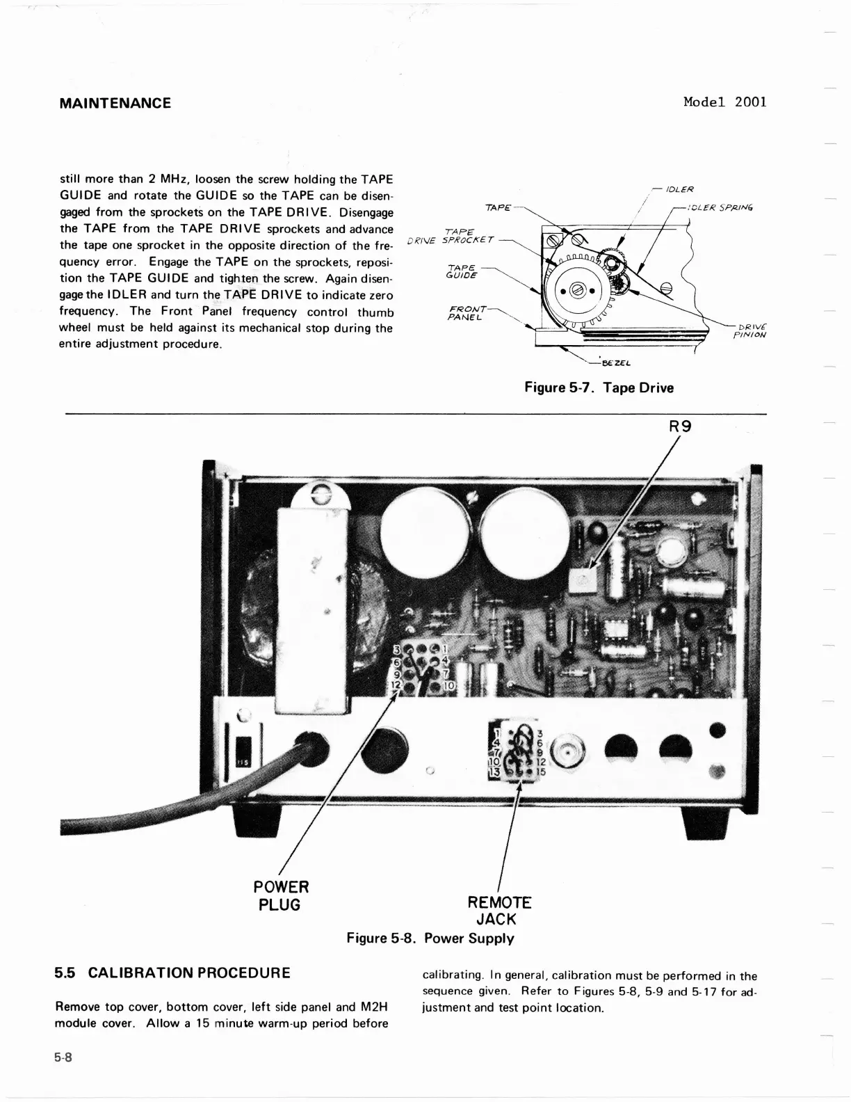
POWER
PLUG
REMOTE
JACK
Figure
5-8.
Power Supply
5.5
CALIBRATION PROCEDURE
calibrating. In general, calibration must be performed in the
sequence given. Refer to Figures
5-8,
5-9
and
5-17
for
ad-
Remove top cover, bottom cover, left side panel and
M2H
justment and test point location.
module cover. Allow a
15
minute warm-up period before
MAINTENANCE
still
more
than 2
MHz,
loosen the screw
holding
the
TAPE
GUIDE
and
rotate
the
GUIDE
so
the TAPE can
be
disen-
gaged
from
the sprockets on the
TAPE
DR I
VE.
Disengage
the
TAPE
from
the
TAPE
DRIVE
sprockets and advance
the tape one sprocket in
the
opposite
direction
of
the fre-
quency error. Engage the
TAPE
on
the sprockets, reposi-
tion
the
TAPE
GUI
DE and tighten the screw. Again disen-
gage
the
IDLER
and
turn
th
.
~
TAPE
DRIVE
to
indicate zero
frequency. The
Front
Panel frequency
control
thumb
wheel
must
be
held against its mechanical stop
during
the
entire
adjustment
procedure.
TAPE
TAPE
DR/
V£
SPROCKET
TAPE
GUIDE
FRONT~
PANEL
-'''-
.
Model 2001
r-
IDLER
:CL£R
SPl<JN6
Figure 5-7. Tape Drive
R9
DI<IV.f'
PINION
POWER
PLUG
REMOTE
JACK
Figure 5-8. Power
Supply
5.5
CALIBRATION
PROCEDURE
Remove
top
cover,
bottom
cover,
left
side panel and
M2H
module
cover.
Allow
a 15
minute
warm-up period before
5-8
calibrating.
In
general,
calibration
must
be
performed in the
sequence
given.
Refer
to
Figures
5-8,
5-9
and
5-17
for
ad-
justment
and test
point
location.