Model
2001
MAINTENANCE
L!%?
d5.5.1 +l8 VOLT ADJUSTMENT
/
6
B
~1g
Connect the digital voltmeter to the +18 volt supply, pin 6
on the power plug and adjust
R9 to produce +18V
f
1
OmV.
(See Figure 5-8).
4.5.2
-18 VOLT CHECK
-18
,
D
,/6
Connect the digital voltmeter to the -18 volt supply, pin
4
on power plug. The reading must be -18 volts *50mV.
P
5.5.3 -20 VOLT CHECK
20.3/
Connect the digital voltmeter to the 20 volt supply, pin 5
on the power plug. The reading must be -20 volts
k0.3V.
/5.5.4
-16 VOLT CHECK
/6
,005
CAUTION
:
The
+
and ~16 volt supplies are not short cir-
cuit protected. Connect the digital voltmeter to the -16
volt supply, pin
3
of the remote jack.
It
must read -16
volts
+-0 1 volt. (Record reading).
LINEARITY
REFEPENCE
SWEEP
WIDTH
ADJ
CENT
SIZE
BAN01
4
3
Connect the digital voltmeter to the +16 volt supply, pin 2
of the remote jack, and adjust R95 (see Figure 5-9) to ob-
tain exactly the same voltage, but of opposite polarity, as
recorded for the -16 volt supply in paragraph
5.5.4.
5.5.6 SWEEP RATE ADJUSTMENTS
-
MODULE M1H
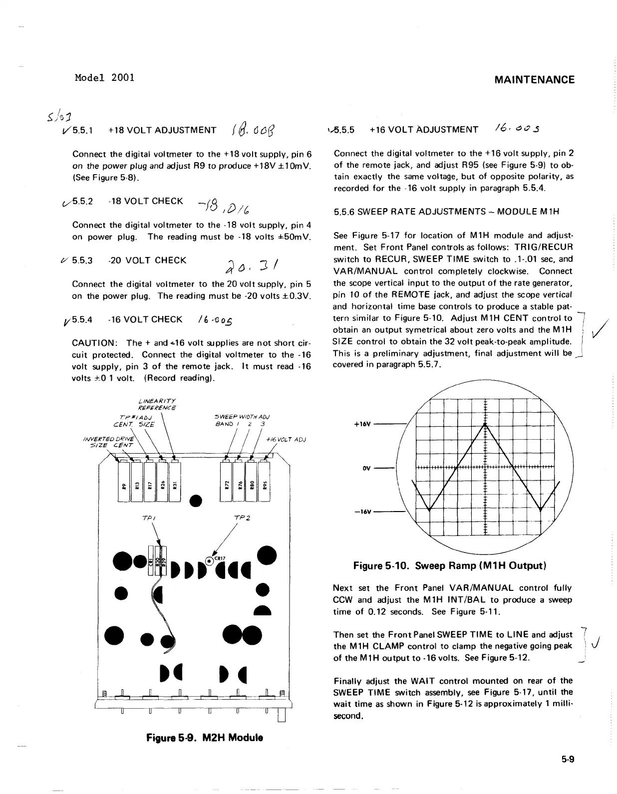
See Figure 5-17 for location of M1H module and adjust-
ment. Set Front Panel controls as follows:
TRIGIRECUR
switch to RECUR, SWEEP TlME switch to .l-.O1 sec, and
VARIMANUAL control completely clockwise. Connect
the scope vertical input to the output of the rate generator,
pin 10 of the REMOTE jack, and adjust the scope vertical
and horizontal time base controls to produce a stable pat-
tern similar to Figure 5-10. Adjust
M1H CENT control to
7
obtain an output symetrical about zero volts and the M1H
1
i
SIZE control to obtain the 32 volt peak-to-peak amplitude.
1
This is a preliminary adjustment, final adjustment will be
-,
J
covered in paragraph 5.5.7.
Figure
5-10.
Sweep Ramp
(M1H
Output)
Next set the Front Panel VAR/MANUAL control fully
CCW and adjust the
MtH INTIBAL to produce a sweep
time of 0.12 seconds. See Figure 5-1 1.
Then set the Front Panel SWEEP TlME to
LINE and adjust
7
the M 1H CLAMP control to clamp the negative going peak
'
J
of the M1H output to -16 volts. See Figure 5-12.
-
Finally adjust the WAIT control mounted on rear of the
SWEEP TlME switch assembly, see Figure 5-17, until the
wait time as shown in Figure 5-12 isapproximately 1 milli-
second.
Figure
5-9.
M2H Module
Model 2001
/
~;1J1
+18
VOLT
ADJUSTMENT
f
8.
(J
{H]
V5.5.1
Connect the
digital
voltmeter
to
the
+18
volt
supply,
pin
6
on
the
power
plug and adjust R9
to
produce +
18V
± 10m
V.
(See
Figure 5·8).
0.
5
.2
-18
VOLT
CHECK
Connect the
digital
voltmeter
to
the -18
volt
supply,
pin
4
on
power plug. The reading
must
be
-18
volts
±.50mV.
/yO 5.5.3
-20
VOLT
CHECK
Connect
the
digital
voltmeter
to
the
20
volt
supply,
pin
5
on the
power
plug.
The
reading
must
be
·20
volts
±0.3V.
V5.5.4 -16
VOLT
CHECK
I
~
,'oo.S
CAUTION:
The
+
and
...
16
volt
supplies
are
not
short cir-
cuit
protected. Connect the
digital
voltmeter
to
the -16
volt
supply,
pin
3
of
the remote jack.
It
must
read -16
volts
+_0
1
volt.
(Record reading).
L.INEARITY
IC€FEICENCE
•
5W€€P
WIDTH AD,)
BAND
I 2 3
TPI
,P2
••
~,
ttt~.·
• •
-
Figure 5-9.
M2H
Module
MAINTENANCE
1.-5.5.5
+16
VOLT
ADJUSTMENT
Connect the
digital
voltmeter
to
the
+ 16
volt
supply, pin 2
of
the remote jack, and adjust R95
(see
Figure 5-9)
to
ob-
tain
exactly
the
same
voltage,
but
of
opposite
polarity,
as
recorded
for
the -16
volt
supply in paragraph 5.5.4.
5.5.6 SWEEP
RATE
ADJUSTMENTS
-
MODULE
M1H
See
Figure 5-17
for
location
of
M1H
module
and adjust-
ment. Set
Front
Panel
controls
as
follows:
TR
I
G/R
ECU R
switch
to
RECUR,
SWEEP
TIME
switch
to
.1-.01
sec,
and
VAR/MANUAL
control
completely
clockwise. Connect
the scope vertical
input
to
the
output
of
the rate generator,
pin
10
of
the
REMOTE
jack. and adjust the scope vertical
and
horizontal
time
base
controls
to
produce a stable pat-
tern
similar
to
Figure 5-10.
Adjust
M1H
CENT
control
to
obtain
an
output
symetrical
about
zero
volts
and the M 1 H
SIZE
control
to
obtain
the
32
volt
peak-to-peak amplitude.
This
is a
preliminary
adjustment,
final
adjustment
will
be
covered
in
paragraph 5.5.7.
~
~
/
I~
+16V
/
\
I
;:
\
/
~
-
/
\
--
7'
\
\
-1=\
I
\
1/
k'iJ
.\
L ___
~
_L-:;
V
~
OV
-16V
Figure 5-10. Sweep Ramp
(M1H
Output)
Next
set the
Front
Panel
VAR/MANUAL
control
fully
CCW
and adjust the
M1H
INT/BAL
to
produce a sweep
time
of
0.12
seconds.
See
Figure 5-11.
Then set the
Front
Panel SWEEP
TIME
to
LINE
and adjust
the M 1 H
CLAMP
control
to
clamp the negative going peak
of
the
M1H
output
to
-16 volts.
See
Figure 5-12.
Finally
adjust the
WAIT
control
mounted
on rear
of
the
SWEEP
TIME
switch assembly.
see
Figure 5-17.
until
the
wait
time
as
shown in Figure 5-12
is
approximately
1
milli-
second.
5-9
7
J