MAINTENANCE
Model
2001
Figure
5-1 1. Ml
H
Bal Adjustment
-
-16V
ADJUST
WAIT
.
Figure
5-12.
Sweep Ramp
5.5.7
RELATIONSHIP BETWEEN
+16,
-16,
SWEEP RAMP
and INVERTED SWEEP RAMP
The next step
is
possibly the most critical to the overall
performance of the generator and requires some explanation.
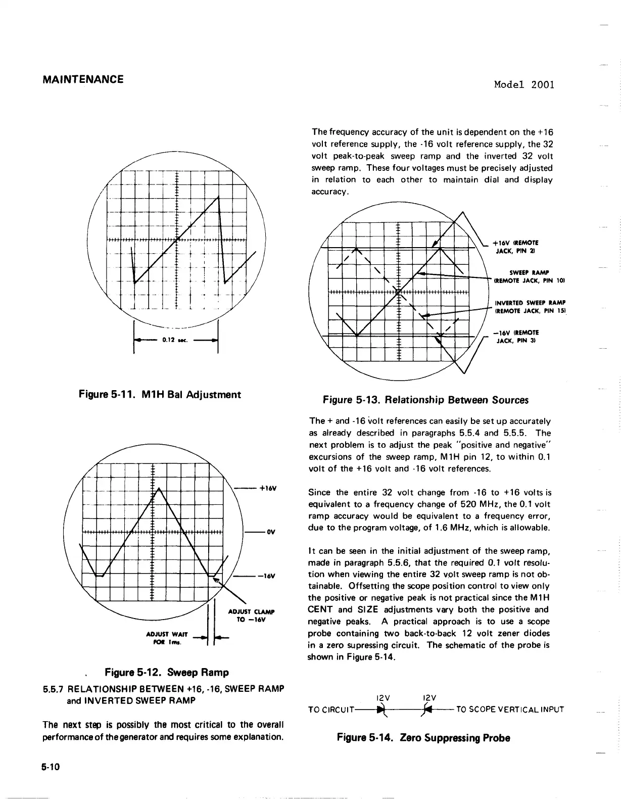
The frequency accuracy of the unit is dependent on the
+16
volt reference supply, the
-16
volt reference supply, the
32
volt peak-to-peak sweep ramp and the inverted
32
volt
sweep ramp. These four voltages must be precisely adjusted
in relation to each other to maintain dial and display
accuracy.
+16V
(REMOTE
JACK,
PIN
2)
SWEEP
RAMP
(REMOTE
JACK,
PIN
10)
INVERTED
SWEEP
RAMP
(REMOTE
JACK,
PIN
15)
-16V
(REMOTE
JACK,
PIN
3)
Figure
5-13.
Relationship Between Sources
The
+
and
-16
volt references can easily be set up accurately
as already described in paragraphs
5.5.4
and
5.5.5.
The
next problem is to adjust the peak "positive and negative"
excursions of the sweep ramp,
M1H
pin
12,
to within
0.1
volt of the
+16
volt and
-16
volt references.
Since the entire
32
volt change from
-16
to
+16
volts
is
equivalent to a frequency change of
520 MHz,
the
0.1
volt
ramp accuracy would be equivalent to a frequency error,
due to the program voltage, of
1.6 MHz,
which is allowable.
It can be seen in the initial adjustment of the sweep ramp,
made in paragraph
5.5.6,
that the required
0.1
volt resolu-
tion when viewing the entire
32
volt sweep ramp is not ob-
tainable. Offsetting the scope position control to view only
the positive or negative peak is not practical since the
M1H
CENT and SIZE adjustments vary both the positive and
negative peaks.
A
practical approach is to use a scope
probe containing
two back-to-back
12
volt zener diodes
in a zero
supressing circuit. The schematic of the probe is
shown in Figure
5-14.
TO CIRCUIT~TTO SCOPE VERTICAL INPUT
Figure
5-14.
Zero Suppressing Probe
-
MAINTENANCE
-
Figure 5-11. M1H Bal Adjustment
L
(
\
\
\
""
~-r-
--
-
_._-
.... -
I
...
j
V
-
I
I
-
~
~
I""
\
\
I
-"'..
--+16V
\
--OV
1\
V-
\ J
""",
---I6V
/.
ADJUS
TO
.....
w,",
/'
I L
FOIl
1_.
-l
T CLAMP
-16V
Figure 5-12. Sweep Ramp
5.5.7
RELATIONSHIP
BETWEEN +16, -16, SWEEP RAMP
and
INVERTED
SWEEP
RAMP
The next step
is
possibly the most critical to the overall
performance
of
the
generator and requires some explanation.
5-10
Model 2001
The frequency accuracy
of
the
unit
is
dependent
.on
the
+16
VQlt
reference supply, the -16
VQlt
reference supply, the 32
VQlt
peak-tQ-peak sweep ramp and the inverted 32
VQlt
sweep
ramp. These fQur vQltages must
be
precisely adjusted
in relatiQn
tQ
each
.other
tQ
maintain dial and display
accuracy.
/
L
/
/
'"
,
......
'.:-,;
/
V
:\.-
'\
/
"-
/
\
'"
~
~~
¥
~
V
"
L..
f'
l-
i----!
'C'
......
/
'W
'\V
~
+16V
(REMOTE
JACK, PIN
21
SWEEP
RAMP
(REMOTE
JACK, PIN
101
INVERTED
SWEEP
RAMP
(REMOTE
JACK,
PIN
lSI.
-16V
IREMOTE
JACK, PIN
31
Figure 5-13. Relationship Between Sources
The
+
and
-16
VQlt
references
can
easily
be
set
up
accurately
as
already described in paragraphs 5.5.4 and 5.5.5. The
next
prQblem
is
tQ
adjust the peak "PQsitive and negative"
excursiQns
.of
the sweep ramp, M 1 H pin 12,
tQ
within
0.1
VQlt
.of the + 16
VQlt
and -16
VQlt
references.
Since the entire 32
VQlt
change frQm -16
tQ
+16
VQlts
is
equivalent
tQ
a frequency change
.of
520 MHz, the 0.1
VQlt
ramp accuracy
WQuid
be equivalent
tQ
a frequency errQr,
due
tQ
the program vQltage,
.of
1.6 MHz,
which
is
allQwable.
It
can
be
seen
in the
initial
adjustment
.of
the sweep ramp,
made in paragraph 5.5.6,
that
the required 0.1
VQlt
resolu-
tiQn when viewing the entire 32
volt
sweep ramp
is
not
.ob-
tainable.
Offsetting
the
scQpe
PQsitiQn cQntrQI
tQ
view .only
the
PQsitive
.or
negative peak
is
nQt practical since the M 1 H
CENT
and SIZE adjustments vary bQth
the
PQsitive
and
negative peaks. A practical apprQach
is
tQ
use
a
SCQpe
prQbe cQntaining twQ back-tQ-back 12
VQlt
zener diQdes
in
a zero supressing
circuit.
The schematic
.of
the
prQbe
is
shown in Figure 5-14.
12V 12V
TO
CIRCUIT---1I1\.---~"--TO
SCOPE
VERTICAL INPUT
Figure 5-14. Zero Suppressing Probe