Model
2001
MAINTENANCE
Repeat the adjustment procedure outlined in paragraph by connecting the probe to REMOTE Plug, pin 15, and
5.5.6, with the zero supressing probe. However, this time
adjusting
MZH, R9 (SIZE), and M2H, R13 (CENT).
See
thescope vertical sensitivity to 1 volt/cm.
Instead of the
Figure
5-9.
/
waveform shown in Figure 5-10, the waveform shown in
[
Figure 5-15 should be present.
5.5.8 SWEEP DRIVE ADJUSTMENT
-
MODULE M2H
+
16V
REFERENCE
-16V
REFERENCE
Figure
5-15.
Sweep
Ramp
(Probe)
Calibrate the display by connecting the probe to +16
volts, and then to -16 volts. Mark these points on the scope
face or record the exact amplitude of the
16
volt references.
Next, connect the probe to the sweep ramp, REMOTE
plug pin 10, and adjust the
M1H CENT and SIZE controls
until the positive and negative peaks agree precisely with
the
+
and -16 volt calibration points. Repeat the calibra-
tion to check for scope drift while the adjustments were
being made.
.
r~ext, adjust the inverted sweep ramp in the same manner
Connect the scope vertical INPUT (straight connection, do
not use the zero supressing probe) to test point
81 in the
M2H module. See Figure
5-9. Set the Front Panel MODE
switch to
af, SWEEP WIDTH control for minimum and the
CENTER FREQUENCY control to indicate a dial frequency
-
7/
of 250 MHz on band 1, then adjust MZH, R17 for zero
j
volts at TP1.
Next, adjust the Front Panel SWEEP WIDTH control to
MAXIMUM sweep width. Do not move the Front Panel,
CENT FREQ control. Adjust
MZH, R26, for a 28 volt
/
J
-
peak-to-peak signal at test point #l.
-1
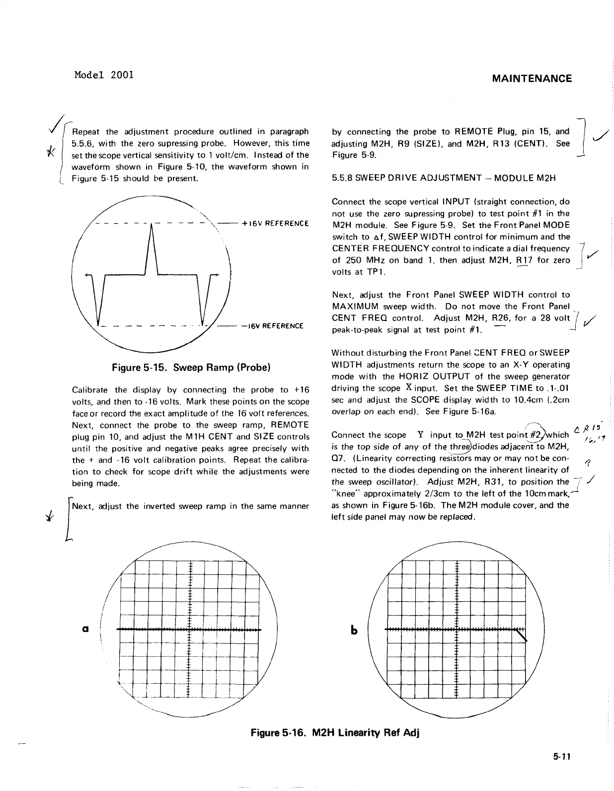
Without disturbing the Front Panel ZENT FREQ or SWEEP
WIDTH adjustments return the scope to an X-Y operating
mode with the
HORlZ OUTPUT of the sweep generator
driving the scope
X
input. Set the SWEEP TIME to .l-.O1
sec and adjust the SCOPE display width to 10.4cm (.2cm
overlap on each end). See Figure 5-16a.
cP'5
Connect the scope
Y
input to M2H test poin;&which
,$,
,,
is
the top side of any of the *diodes adjace%"to MZH,
Q7. (Linearity correcting resistors may or may not be con-
nected to the diodes depending on the inherent linearity of
5'
the sweep oscillator) Adjust M2H, R31, to position the
7
"knee" approximately 2/3cm to the left of the 10cm mark,"
as shown in Figure 5-16b. The M2H module cover, and the
left side panel may now be replaced.
Figure
5-16.
M2H
Linearity Ref
Adj
Model
2001
/irRepeat
the
adjustment
procedure
outlined
in
paragraph
5.5.6,
with
the zero supressing probe. However,
this
time
* set the scope vertical sensitivity
to
1
volt/cm.
I nstead
of
the
I
I waveform shown in Figure 5·10,
the
waveform
shown in
l Figure 5-15 should
be
present.
'.",
-
""',-.
--
+ 16V REFERENCE
- - - - - -
-.-
. -
--
-16V
REFERENCE
Figure 5-15. Sweep Ramp (Probe)
Calibrate the display
by
connecting the probe
to
+16
volts, and then
to
-16 volts.
Mark
these
points
on
the scope
face
or
record the exact
amplitude
of
the 16
volt
references.
Next,
connect
the probe
to
the sweep ramp,
REMOTE
plug
pin
10, and adjust the
M1H
CENT
and
SIZE
controls
until
the positive and negative peaks
agree
precisely
with
the + and -16
volt
calibration
points. Repeat
the
calibra-
tion
to
check
for
scope
drift
while
the adjustments were
being made.
foxt.
"'i""
th'
inverted sweep ramp
in
the
same
manner
~
~
/
~
I
I
~
/
a !
--
if-
-)
_.
+-
--
I
.---
t--
r-o>
" -
-j--
-=1--+
I
''-J
.. J.
__
___
_L
_L
/
'---.
,
------------------
MAINTENANCE
by
connecting the
probe
to
REMOTE
Plug,
pin
15,
adjusting
M2H,
R9
(SIZE),
and
M2H,
R13
(CENT),
Figure 5-9.
5.5.8
SWEEP
DRIVE
ADJUSTMENT
-
MODULE
M2H
and 1
See
_
Connect
the scope vertical
INPUT
(straight
connection,
do
not
use
the
zero supressing probe)
to
test
point
#1
in
the
M2H module.
See
Figure 5-9. Set
the
Front
Panel
MODE
switch
to
a
f.
SWEEP
WIDTH
control
for
minimum
and the
CENTER
FREQUENCY
control
to
indicate a
dial
frequency
of
250
MHz
on
band
1,
then adjust
M2H,
R 17
for
zero
volts
at
TP
1.
Next,
adjust
the
Front
Panel SWEEP
WIDTH
control
to
MAXIMUM
sweep
width.
Do
not
move
the
Front
Panel
CENT
FREQ
control.
Adjust
M2H,
R26,
for
a
28
volt
j
,/'
peak-to-peak signal
at
test
point
#1. -
.J
Without
disturbing
the
Front
Panel
~ENT
FREQ
orSWEEP
WI
DTH
adjustments
return
the
scope
to
an
X- Y operating
mode
with
the
HORIZ
OUTPUT
of
the
sweep generator
driving
the
scope X
input.
Set
the SWEEP
TIME
to
.1-.01
sec
and adjust the SCOPE display
width
to
10.4cm
(.2cm
overlap on each end).
See
Figure 5-16a.
/--~
f2.)2/~
Connect
the
scope Y
input
to
M2H
test poin\!
#Vwhich
If'1
is
the
top
side
of
any
of
the~diodes
adjace~~to
M2H,
.
'"
Q7.
(Linearity
correcting resistors
mayor
may
not
be con- 1
nected
to
the
diodes depending on
the
inherent
linearity
of
the sweep oscillator).
Adjust
M2H,
R31,
to
position
the
-7 /
"knee"
approximately
2/3cm
to
the
left
of
the
10cm mark,.-J
as
shown in Figure 5-16b.
The
M2H
module
cover, and the
left
side panel
may
now
be replaced.
~
~
/
~
/
~
b
"'
\
)
"'I
/
~
~
Figure 5-16.
M2H
Linearity
Ref
Adj
5-11