90 CHAPTER 9 VERIFICATION
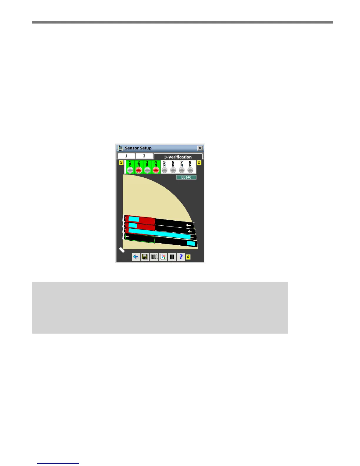
Vehicle detections in a stopped queue are represented by a stationary light blue rectangle.
Channel Indicators
When detections enter a zone, they will cause the indicators for the channel mapped to that
zone to turn red. To see the zones mapped to a particular channel, select that channel by
clicking on its indicator (see Figure 9.2). Active zones for the selected channel will be red;
inactive zones for the selected channel will be gray. e channel type will be indicated by
the letter under the channel number (C = Counting, N = Normal, P = Pulse). An “I” will
also be added if the channel is inverted. Click on the yellow button on either side of the
channel indicators to see channels 9–16.
Figure 9.2 – Channel Verification
Note
Only the zones for selected channels will appear. If zones are not mapped to any
channel, they will not be seen in the Verification window.
To see the delay/extend, logic and detector input/phase settings for a single zone, click and
hold on a channel indicator and the following window will appear (see Figure 9.3).