7
November 2008 Part No. 920559 Rev H
2.5 Lifting and Installing the Dispenser
Remove the shipping carton from the dispenser and, if the dispenser is equipped with an optional val-
ance, survey the site to determine if it should be installed before or after the dispenser is set on the
island. Wayne recommends installing the valance after the dispenser is installed, if practical, to protect it
from installation damage. See the Valance Module drawing in the back of this manual.
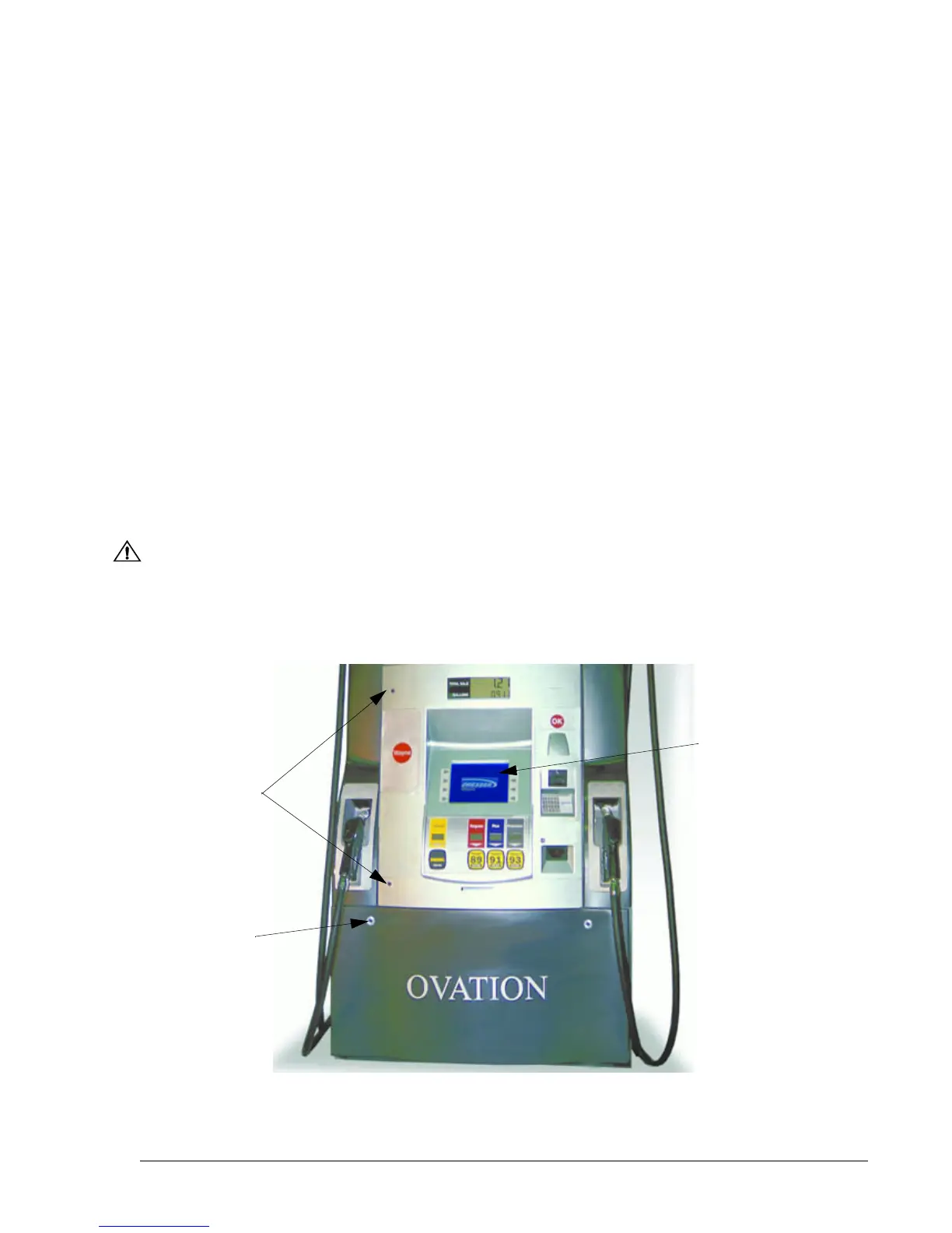
Use door key (p/n 1-202022) to unlock and then remove the lower doors, see Figure 2-3 for location.
Install (2) eye-bolts in the dispenser top castings and lift the dispenser onto the island as per Lifting
Instructions drawing 888514-001 in Appendix B. When handling Ovation dispensers, lift only as per the
Lifting Instructions drawing contained in this manual. Do not lift by the electronic enclosure, nozzle
boot, or any external panels.
Bolt the dispenser into place (Section 2.2), remove the shipping discs from the meter inlets and connect
the product piping per the appropriate Installation Instruction drawing in Appendix B. When installing a
blending dispenser, make sure the Lo and Hi product inlets (and, if applicable, the single product inlet)
are correctly located.
To ensure tight, leak-proof connections when making piping connections, wash all cutting oils off the
threads and use a UL-classified pipe joint sealing compound, rated for use with petroleum-based prod-
ucts.
WARNING
Explosive or flammable vapors may accumulate within the dispenser housing. All piping connec-
tions in the final installation must be accurately fitted and all threaded joints tightly made up with a
Listed gasoline-resistant pipe joint compound. Put the compound on male threads only, being
careful not to get excess inside the pipe or fittings. Failure to perform the above will present a haz-
ardous condition that could result in serious injury.
Figure 2-3 DOOR LOCK LOCATIONS. One door key fits upper and lower door locks.
Optional VGA display screen shown.
Upper Door
Locks
VGA
Screen
Option
Lower Door
Locks (2)