8
Part No. 920559 Rev H November 2008
2.6 Electrical Wiring
2.6.1 General
Wayne recommends employing a qualified electrician for all wiring. A hazardous liquid is being handled, so it is
important to ensure that all wiring is in accordance with the National Electrical Code (NFPA 70) as well as all
federal, state and local regulations. Note: U.L. requires that all electrical connections to the dispenser be made
with threaded, rigid conduit and properly sealed conductors. Note: All dispensers and electrical connection
boxes must be grounded per NFPA 70.
2.6.2 Dispenser to Wayne Control System Interconnection
Dispenser installation wiring diagrams are provided in Appendix B. The system interconnection wiring diagrams
supplied are for reference purposes. Use these diagrams along with the wiring diagrams supplied with the control
system for laying out the system wiring requirements for a new site or when making changes to an existing one.
Two data wires to the Data Distribution Cabinet are required for the Wayne control system console operation.
Two data wires to the Site Controller Cabinet are required for dispenser card processing CAT operation.
Two data wires to the Site Controller Cabinet are required for Wayne TRAC operation.
One ethernet cable (gas and oil resistant) is required for dispensers equipped with the IDPOS or iX CAT option
from the switch in the dispenser to the switch in the building, see Section 2.6.6, Figure 2-5 and Figure 2-6. A UL
AWM Ethernet cable, Category 5 or higher, rated at least 300 V, 60 degrees C with a gasoline and oil resistant
jacket may be used. The conduit in the dispenser must be potted at the end of the installation.
Optional equipment wires, see Section 2.6.6.
NOTE: When data wires are installed, only the two data wires from the Data Distribution Cabinet used for pump control
are to be terminated at the dispenser’s terminal strip. The additional data wires should not be physically
connected to the data terminals on the dispenser’s terminal strip. Instead they should be properly terminated
individually using wire nuts.
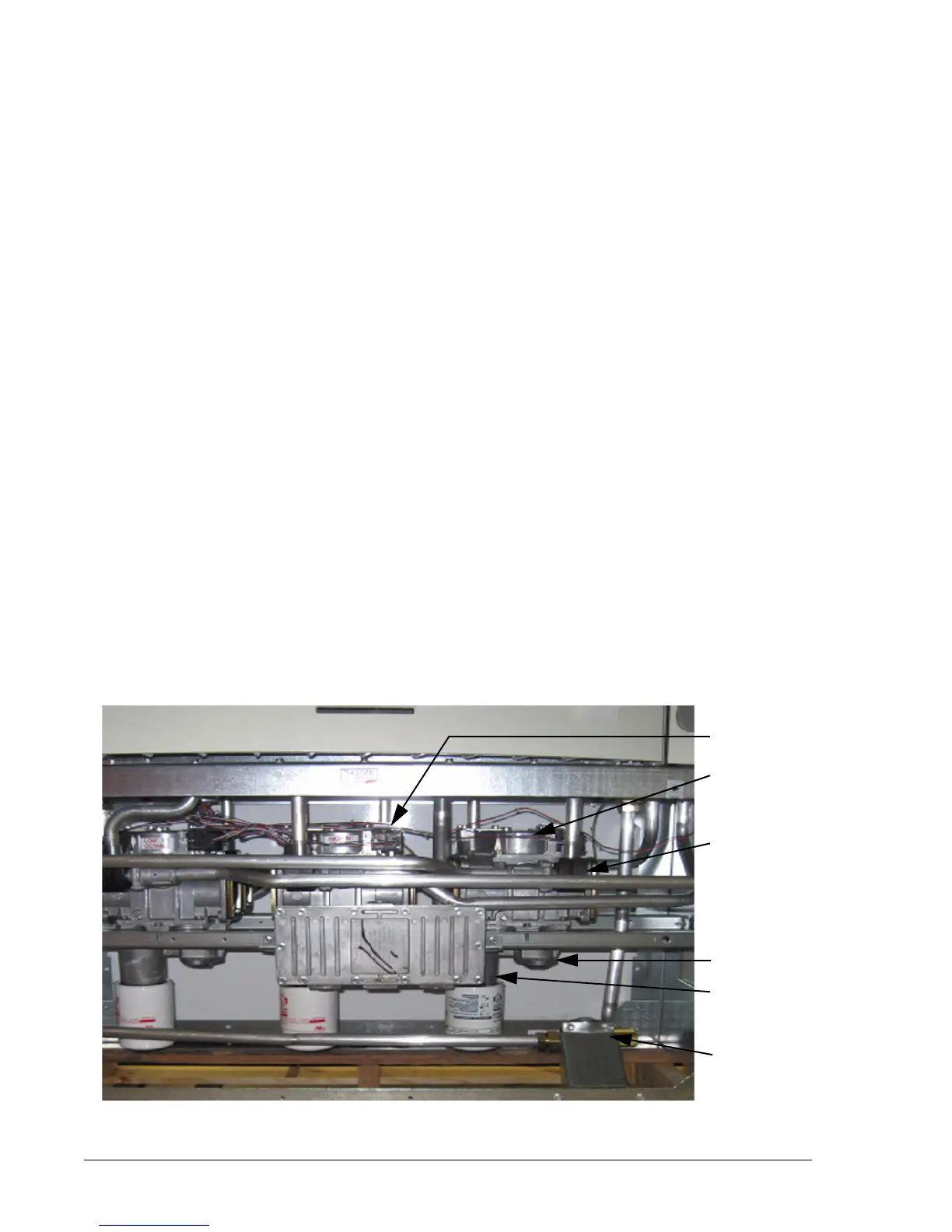
Figure 2-4 shows the location of dispenser components that may need to be accessed during installation. If the
dispenser is not equipped with a junction box in the hydraulic cabinet, field wiring will terminate at the terminal
strip inside the electronic enclosure as shown in Figure 2-5 and the conduit fittings shown will be potted in the
field.
Figure 2-4 Location of Components in Lower Section (iMeter model shown). Side 1.
See Appendix B for new footprint drawings with the smaller junction box (above) effective in November 2008.
JUNCTION BOX
FILETR/STRAINER
VAPOR
PRODUCT INLET
RECOVERY
PROPORTIONAL
VALVE
/
OUTLET
WIP PULSER
E-M TOTALIZERS
CHECK VALVES
(under Valve Plates
in iMeter Dome)
VALVE COIL
CASTING