12
BURNER INSTALLATION
The P250 and P265 power gas burners were designed for converting oil fired furnaces and boilers. Due consideration was given to
making it as simple and easy to install and service as possible without weakening its durability or efficiency. The burner is supplied
as a completely assembled package unit.
NOTE: The burner must be installed in such a manner that all controls will be readily accessible for inspection, cleaning, adjustment
and repairs.
INSTALLATION OF MOUNTING FLANGE
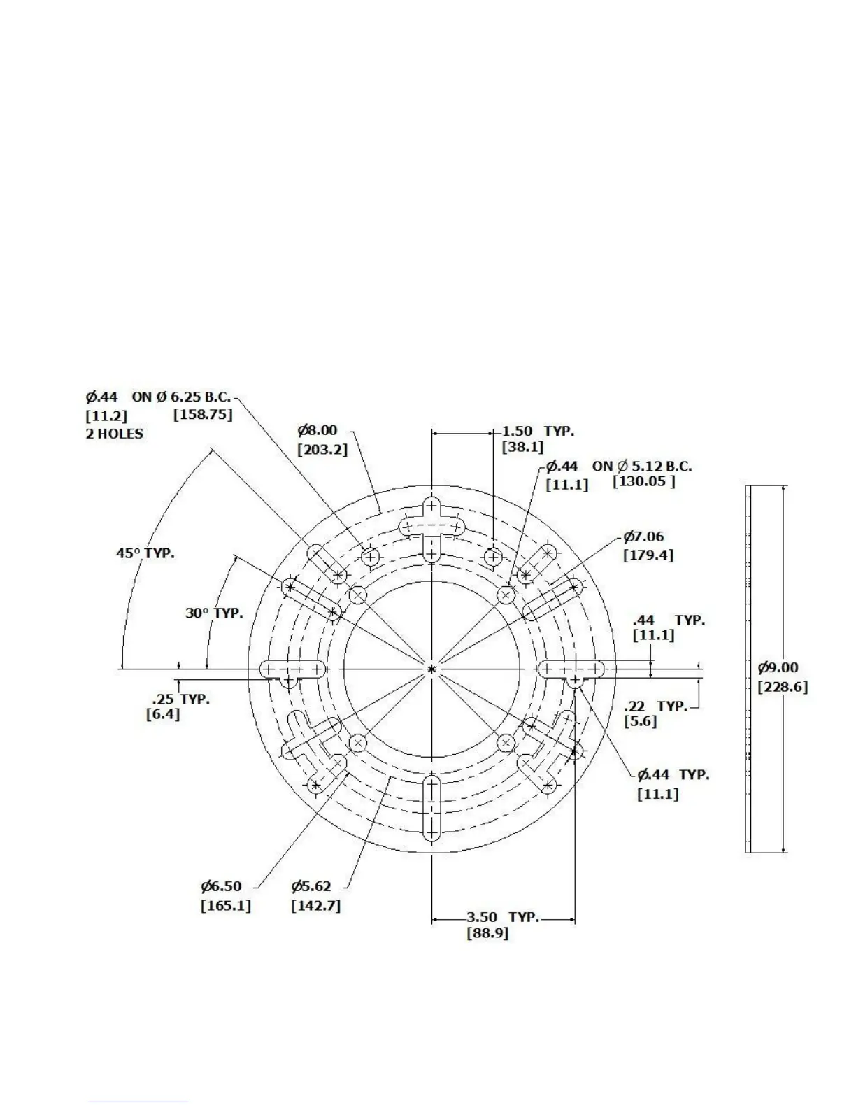
Position the mounting flange on the furnace wall, adjusting orientation as necessary until the bolt pattern of the furnace allows the
flange to sit flush. (See Figure 6 for flange dimensions.)
Note the orientation of the flange and remove it so that the flange gasket may be placed between the furnace wa ll and the flange.
Tighten the flange to the furnace wall.
Insert the burner tube into the flange and position it per Figure 5. Tighten the flange onto the burner tube.
FIGURE 6: ADJUSTABLE MOUNTING FLANGE DIMENSIONS