NOTE: Copper tubing shall comply with standard type K or L of ASTM B 88 or ASTM B 280.
TESTING PIPING FOR LEAKS
Before turning gas under pressure into piping, all openings from which gas can escape should be closed. Immediately after
turning on gas, the system should be checked for leaks. This can be done by watching the 1/2 cubic feet test dial and allowing 5
minutes to show any movement, or by soaping each pipe connection and watching for bubbles. If a leak is found, make the
necessary repairs and repeat the above test. Defective pipes or fittings should be replaced and not repaired.
Never use a flame or fire in any form to locate gas leaks, use a soap solution.
After the piping and meter have been checked completely, purge the system of air. Do not bleed the air inside the furnace. Be sure to
relight all the gas pilots on other appliances.
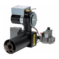
ELECTRICAL WIRING OF BURNER
The conversion burner is shipped completely wired. It is only necessary to supply the 115 volt circuit, thermostat and limit circuit. All
wiring must conform with the National Electric Code or the code legally authorized in the locality where the installation is being made.
The burner, when installed, must be electrically grounded in accordance with local codes or, in the absence of local codes, w ith the
latest edition of the National Electrical Code, ANSI/NFPA No. 70. See wiring diagrams in Figure 22 through Figure 26 for reference on
wiring, thermostat connection, and limit circuit. If an external electrical source is utilized, the conversion burner, when installed, must be
electrically grounded in accordance with local codes or, in the absence of local codes, with the latest edition of the National Electrical
Code ANSI/NFPA No. 70.
The burner ships with a jumper wire on the thermostat (T-T) terminals. Jumper needs to be removed for remote thermostat control and
the thermostat needs to be connected per wiring diagrams. T-T terminal is an open/close switch for the burner and no voltage should
be connected to it. For boilers it may be necessary to leave the T-T terminal jumped as the aquastat may be providing the voltage to the
burner and controlling when voltage is sent to the burner. The burner is controlled by the appliance. Once wiring is complete between
burner and appliance, verify appliance is controlling the burner’s on/off operation. When connecting the burner to the 120 volt electrical
supply, utilize the knockout provided on the burner’s junction box.