27
NORMAL OPERATION CHECK OF BURNER (ELECTRONIC PILOT)
PRELIMINARY CHECK
The following visual checks should be made before troubleshooting an after installation or maintenance.
1. Check the power to the appliance and S8600.
2. Manual shutoff cocks in gas line to appliance must be open.
3. Make certain all wiring connections are clean and tight.
4. S86G, H module must not be in safety lockout. First de-energize the system and wait at least one (1) minute. This resets the
module, allowing a return to start condition.
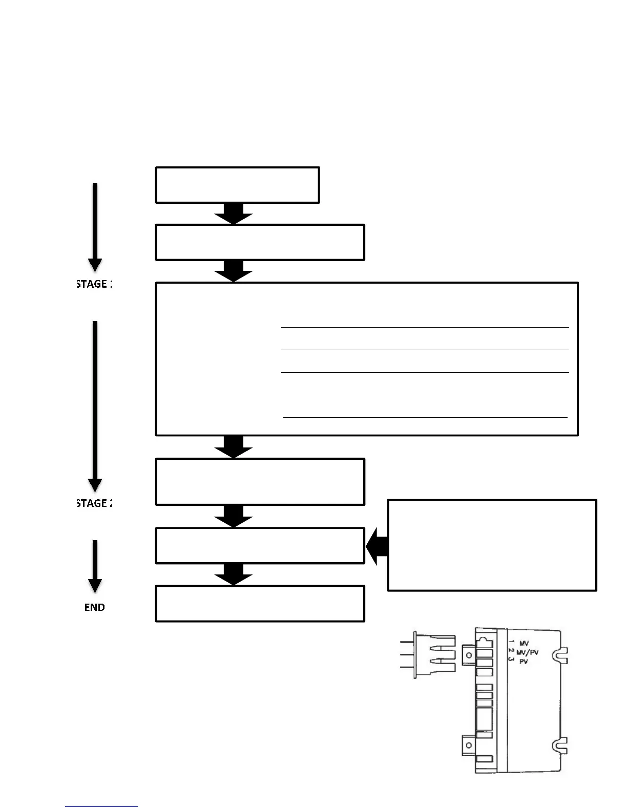
5. Review the S8600 system normal sequence of operation in Figure 19 below.
SEQUENCE OF OPERATION
STAGE 2
MAIN BURNER
OPERATION
THERMOSTAT (CONTROLLER)
CALLS FOR HEAT
SPARK GENERATOR
Powered by First Valve (pilot) operator opens
PILOT BURNER OPERATION
Pilot burner lights. OR Pilot burner does not light
Module senses Module________ Response________________________________________
flame current. S8900A,F Ignition spark continues, pilot valve remains
S8610A,F open until system is reset___________________________
S8600B,H After 15 or 90 seconds a system locks out; must be
S8610B,H manually reset_______ ____________________________
S8600M After one second a system shuts off; after 5 minutes
(6 minutes nom.), module restarts trial for ignition;
ignition trial, shut off, wait sequence repeats until pilot
lights or call for heat ends.__________________________
A shutoff/lockout timing is stamped on module
FLAME CURRENT SENSED
Spark generator off
Second valve operator (main) opens
MAIN BURNER OPERATION
Module monitors pilot flame current.
THERMOSTAT (CONTROLLED) SATISFIED
Valves close, pilot and main burners are off.
POWER INTERRUPTION
System shuts off, restarts when power is
restored.
PILOT FLAME FAILURE
Main valve closes
Module starts trial for ignition.
Low Voltage Wiring
Assembly with
Molex Plug