28
TROUBLESHOOTING GUIDE DIRECT IGNITION
NOTE 1: BURNERS ARE NOT PRESET FROM THE FACTORY AND MUST BE ADJUSTED AT THE SITE.
NOTE 2: NEW GAS LINE INSTALLATIONS WILL HAVE AIR IN THE LINES AND REQUIRE SEVERAL IGNITION
ATTEMPTS TO PURGE ALL THE AIR FROME THE LINES.
NOTE 3: DO NOT ATTEMPT TO PERFORM ANY WORK ON THIS BURNER UNLESS THE FOLLOWING TOOLS ARE
AVAILABLE AND YOU ARE A CERTIFIED INSTALLER:
1. VOLT METER-VOLTS, OHMS, CONTINUITY
2. AMP METER-CLAMP TYPE
3. BURNER MANUAL
4. MANOMETER
5. O
2
OR CO
2
ANALYZER
6. CO TESTER
7. BLADE SCREW DRIVERS
8. NUT DRIVERS
9. OPEN END WRENCHS
10. TAPE MEASURE
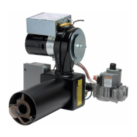
The Wayne Burner that you are attempting to troubleshoot has the following electrical single phase components:
1. 115 Volt Combustion Fan Motor with End Switch
2. Fan Relay-24 volt coil side and 110 volt fan side
3. Honeywell Gas Primary Control (24 volt)
4. Honeywell Gas Valve (24 volt)
5. Transformer- 115 volt side and 24 volt side
6. Ignition Rod/Sensing Rod
7. Ignition Lead
8. T-T (24 volt) terminal
TROUBLESHOOTING GUIDE ELECTRONIC PILOT
(FOR BURNERS UTILIZING HONEYWELL S8600 IGNITION CONTROL)
Start the system by setting the thermostat or controller above required temperature. Observe system response. Establish type of
malfunction or deviation from normal operation. Use Figure 20 to check for normal system operation by following instruction question in
box. If the condition is true or okay (answers yes), go down to next box underneath, if the condition is not true or not okay (answers no),
go right to the next box alongside. Continue checking and answering conditions in each box encountered, until a problem and/or the
repair are explained. After any maintenance or repair, the troubleshooting sequence should be repeated until the troubleshoot ing
procedure ends with normal system operation.
IMPORTANT: The electronic Control Module cannot be repaired. If troubleshooting procedure indicates a malfunction in
the Control Module, it must be replaced. Intermittent pilot systems should be serviced only by trained and experienced
personnel.