Cool Top Trail 20/24 20
NOTE
Before contacting Webasto for technical support please collect the following information:
■
Are any error codes displayed?
■
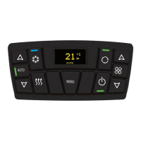
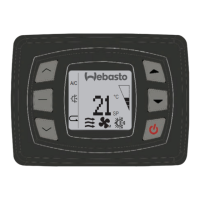
Is the display of the air distributor in normal operation or not? Does it display a temperature from
16 to 30°C?
■
Can you adjust the set point temperature when in cool or heat mode?
■
Is there a “0” shown in the display?
■
Is the display showing a jumbled display?
■
When in fan mode is there any air flow from the air distributor outlets?
■
Can you hear the compressor starting or stopping in heating or cooling mode?
Your help in collecting this information will greatly assist the service team in correcting any problems
– Thank you
8 Disposal
Dispose of packaging material as required by standing regulations, separating them for recycling.
The system cannot be disposed off as regular waste.
Dispose the system according the local applicable rules and regulations. Obtain information about
disposal at the city council, the responsible waste station and/or your local Webasto sales partner.
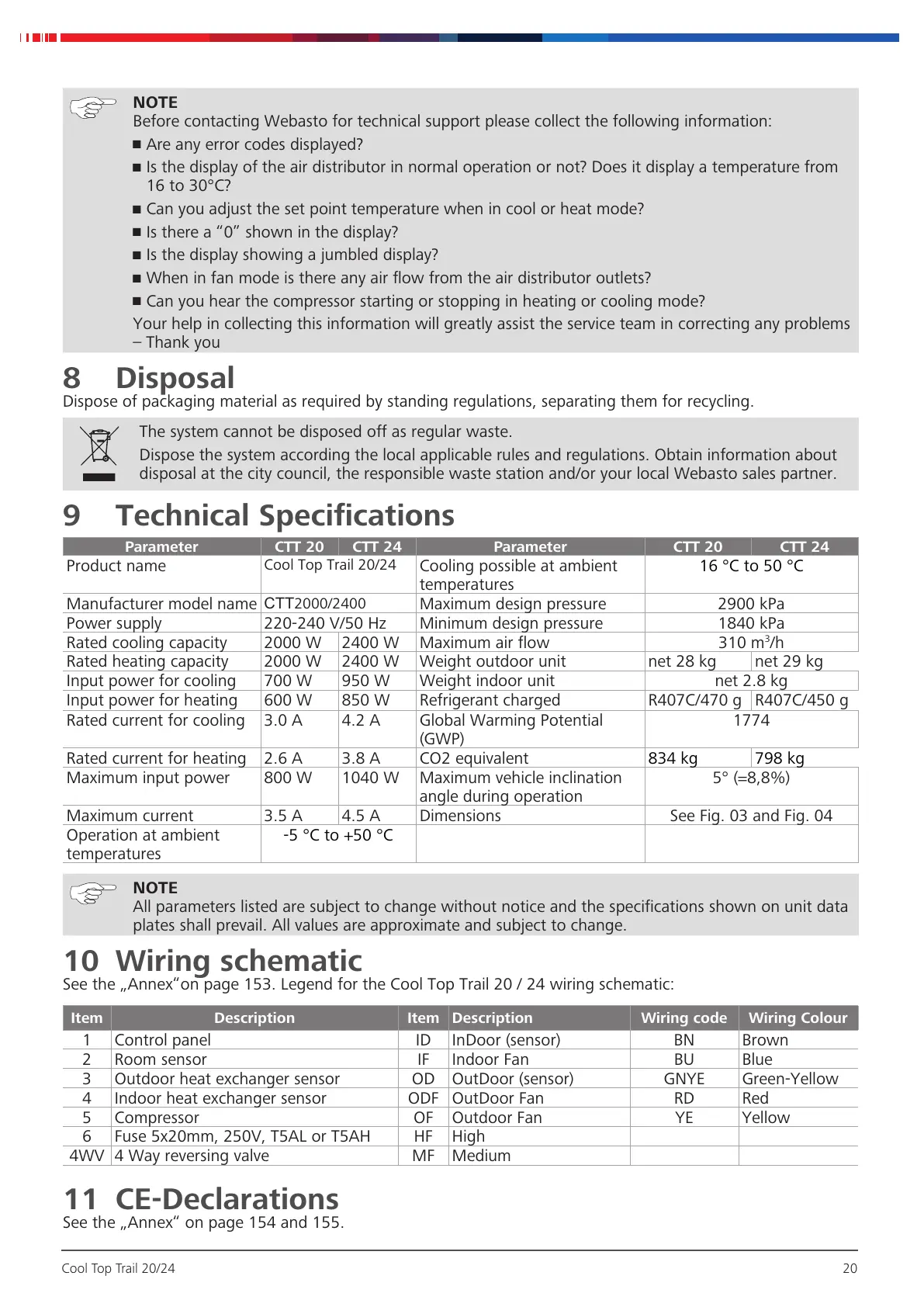
9 Technical Specifications
Parameter CTT 20 CTT 24 Parameter CTT 20 CTT 24
Product name
Cool Top Trail 20/24
Cooling possible at ambient
temperatures
16°C to 50°C
Manufacturer model name
CTT2000/2400
Maximum design pressure 2900kPa
Power supply 220-240V/50Hz Minimum design pressure 1840kPa
Rated cooling capacity 2000W 2400W Maximum air flow 310m
3
/h
Rated heating capacity 2000W 2400W Weight outdoor unit net 28kg net 29kg
Input power for cooling 700W 950W Weight indoor unit net 2.8kg
Input power for heating 600W 850W Refrigerant charged R407C/470g R407C/450g
Rated current for cooling 3.0A 4.2A Global Warming Potential
(GWP)
1774
Rated current for heating 2.6A 3.8A CO2 equivalent
834kg 798kg
Maximum input power 800W 1040W Maximum vehicle inclination
angle during operation
5° (=8,8%)
Maximum current 3.5A 4.5A Dimensions See Fig. 03 and Fig. 04
Operation at ambient
temperatures
-5°C to +50°C
NOTE
All parameters listed are subject to change without notice and the specifications shown on unit data
plates shall prevail. All values are approximate and subject to change.
10 Wiring schematic
See the „Annex“on page 153. Legend for the Cool Top Trail 20 / 24 wiring schematic:
Item Description Item Description Wiring code Wiring Colour
1 Control panel ID InDoor (sensor) BN Brown
2 Room sensor IF Indoor Fan BU Blue
3 Outdoor heat exchanger sensor OD OutDoor (sensor) GNYE Green-Yellow
4 Indoor heat exchanger sensor ODF OutDoor Fan RD Red
5 Compressor OF Outdoor Fan YE Yellow
6 Fuse 5x20mm, 250V, T5AL or T5AH HF High
4WV 4 Way reversing valve MF Medium
11 CE-Declarations
See the „Annex“ on page 154 and 155.
More information https://www.caravansplus.com.au
 Loading...