5
2 Description of data interfaces
2.1 Overview
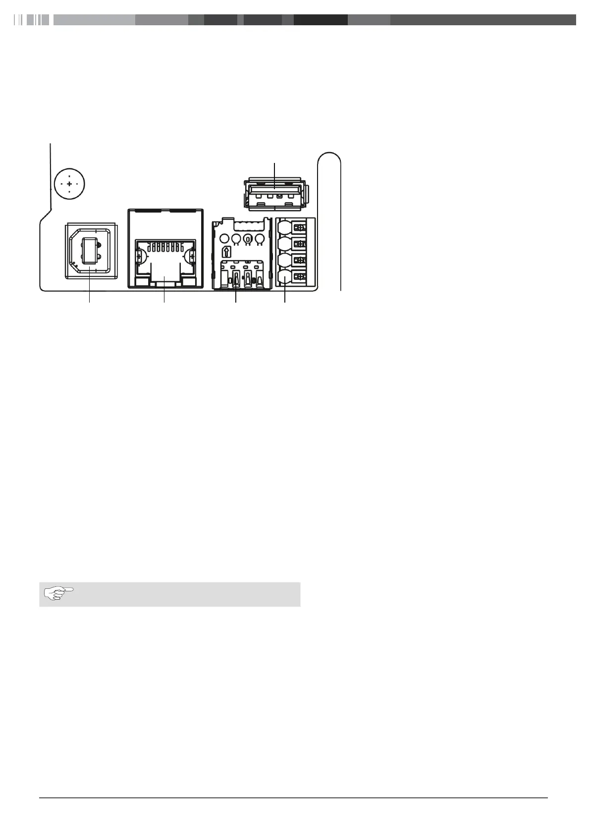
With the cover open, the data interfaces can be found on the left-hand side in the connection area. This area is separated from the
power supply area by a plastic partition wall.
Fig. 01:
1
Pin 1
Overview of interfaces
2.2 USB type A
This connection is used in host mode for a USB stick for software or configuration updates. This connection supports the 5V power sup-
ply up to maximum 100mA.
2.3 RS485 (Modbus) and CP
Overview of push-in terminals from top to bottom:
1. RS485 (GND) – External Modbus
2. RS485 (A, /D) – External Modbus
3. RS485 (B, D) – External Modbus
4. CP line charging cable (control line between vehicle and charging station)
The Modbus data connection to a primary electricity meter can be established for advanced power management. This is done with a
RS485 interface using the top three push-in terminals.
Comply with the following connection parameters at the electricity meter:
■
Insert the RS485 bus cable, sheath dielectric strength 600V, shielded
■
Connection parameter: „10.4 Dynamic Load Management (DLM) (local dynamic load management)“ on page 19
2.4 SIM cardslot for modem
If it is necessary to change a GSM provider, then the SIM card can be removed from the SIM card slot and an alternative SIM card can
be inserted.
NOTE
Not automatically ejected by a spring.
Prerequisites for using a SIM card:
■
Form factor 3FF (micro SIM)
■
A "Machine-to-Machine"-compatible M2M SIM card without PIN enabled by provider
2.5 LAN (RJ-45)
For connecting the charging station to the wired network infrastructure at the installation location. The charging station can be con-
trolled using this connection if there is a connection to the back end or to the local power management system.
2.6 USB type B
Connection for making a USB connection to a computer for configuring the Webasto Live. Connection for making a USB connection to
a computer for configuring the Webasto Live. The USB connection functions as a network interface that allows you to access the web
configuration interface.