15
Peugeot 207 / 207 SW / 207 CC
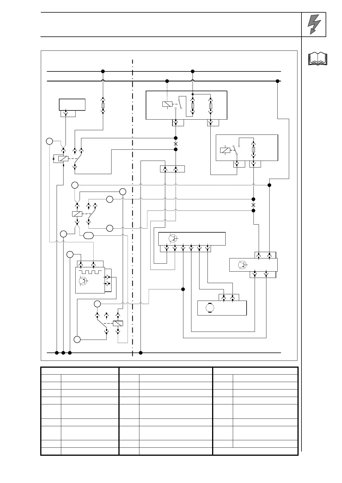
Wiring diagram of automatic air-conditioning Variant 2
Wiring dia-
gram
Webasto components Vehicle components Colours and symbols
Legend
HG TT-C/E Heater 8050 Fan motor rt red
X1 6-pin connector PSF1 Main power supply ws white
F3 Fuse 8045 Fan controller sw black
K3 Fan relay 8080 A/C control panel br brown
K3.1 Additional relay BSI1 Central electrical box for
passenger compartment
gn green
K3.2 Additional relay IC 26 6-pin connector ro pink
IPCU Pulse width modula-
tor
gr gray
X Cutting point
Wiring colours may vary.
gn/
ws
ws
sw
rt/ws
rt
Webasto
31
30
15
Peugeot
ws
rt
HG
4
X1
F3
86
85 30
87a87
K3
IC26
4 3
BSI 1
F14
R7
2
2V GR
6
10V NR
PSF 1
F11
R7
MF5
2
2V NR
5
8V NR
sw
86
85 30
87a87
K3.1
sw
rt
rt
ro
ro
gr
br
br
8685
A
E
IPCU
br
gn/
ws
rt
sw
rt
rt
rt
4
3
5
7
9
1
8
6
86
8530
87a 87
K3.2
2
10
br
8045
6V NR
214536
18V NR
18
3
40V BE
40 39
8080
8050
2V NR
2
1
M

 Loading...