11 | Electrical Connections
11.2.1
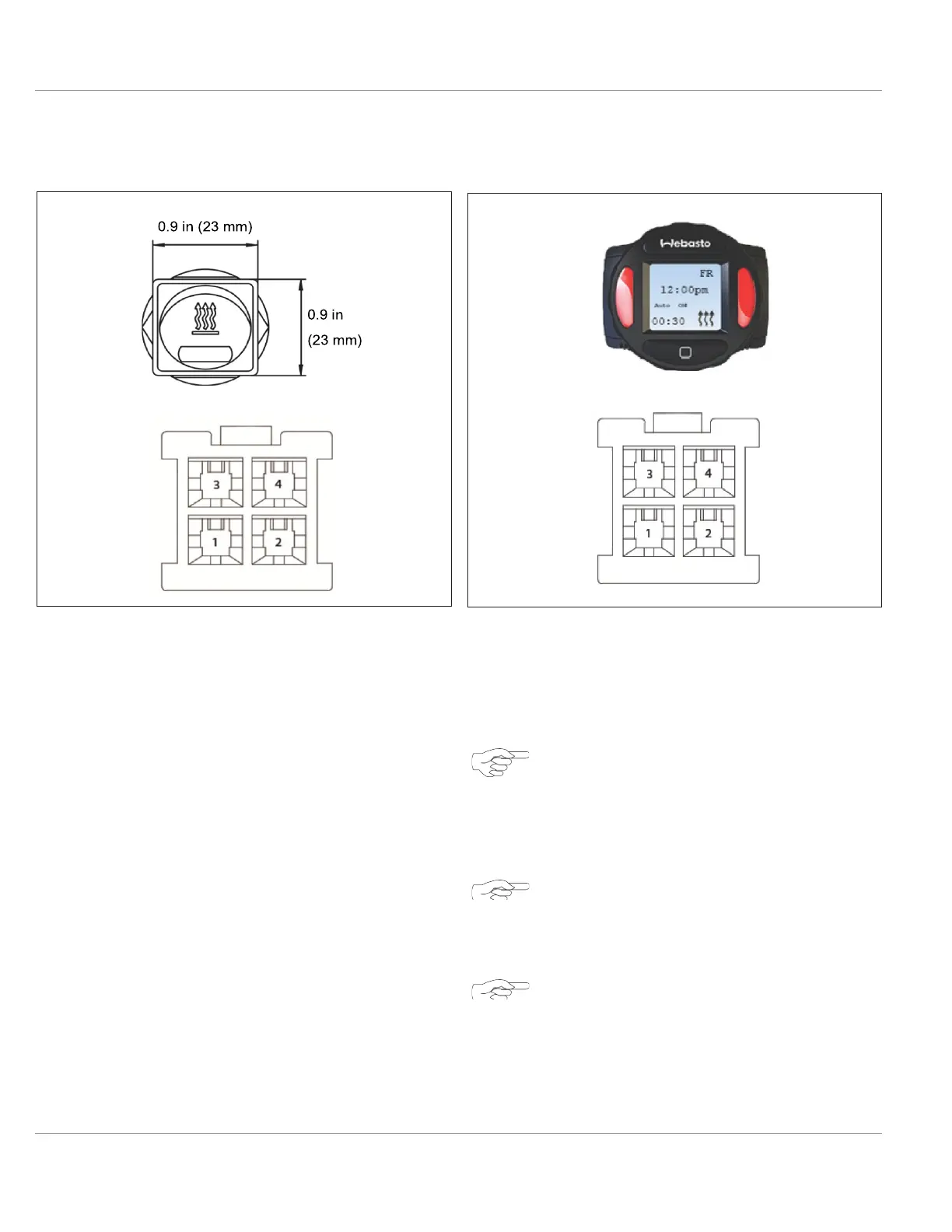
Rocker Switch Installation
11.2.2
SmarTemp 2.0 fx Installation
Fig. 29: Rocker Switch Installation
1 Red (power) 2 Brown (ground)
Fig. 30: SmarTemp 2.0 fx Connections
1 Red (power) 2 Brown (ground)
3
Black or Grey (ON/
OFF signal)
4
Green (diagnostic
blink code)
3
Black or Grey (ON/
OFF signal)
NOTE
4
Green (diagnostic
blink code)
1.
Select a suitable location in the vehicle for the
ON/OFF rocker switch to mount.
2.
Drill a ¾ in (19 mm) hole for the switch.
3.
Route the harness between the heater and the
switch, secure the harness along its length with
wire ties. If possible, use an existing hole in the
bulkhead or drill a hole in a suitable location. Pro-
tect the harness with a grommet at the bulkhead.
4.
Connect the electrical connector to the switch.
Always make sure there are no obstacles
behind the mounting location prior to
drilling.
NOTE
Ensure good readability when selecting in-
stallation location.
NOTE
Observe information on adhesive labels and
colored markings when connecting the
control element to vehicles wiring harness.

 Loading...


