12 | Wiring Diagrams
12.6
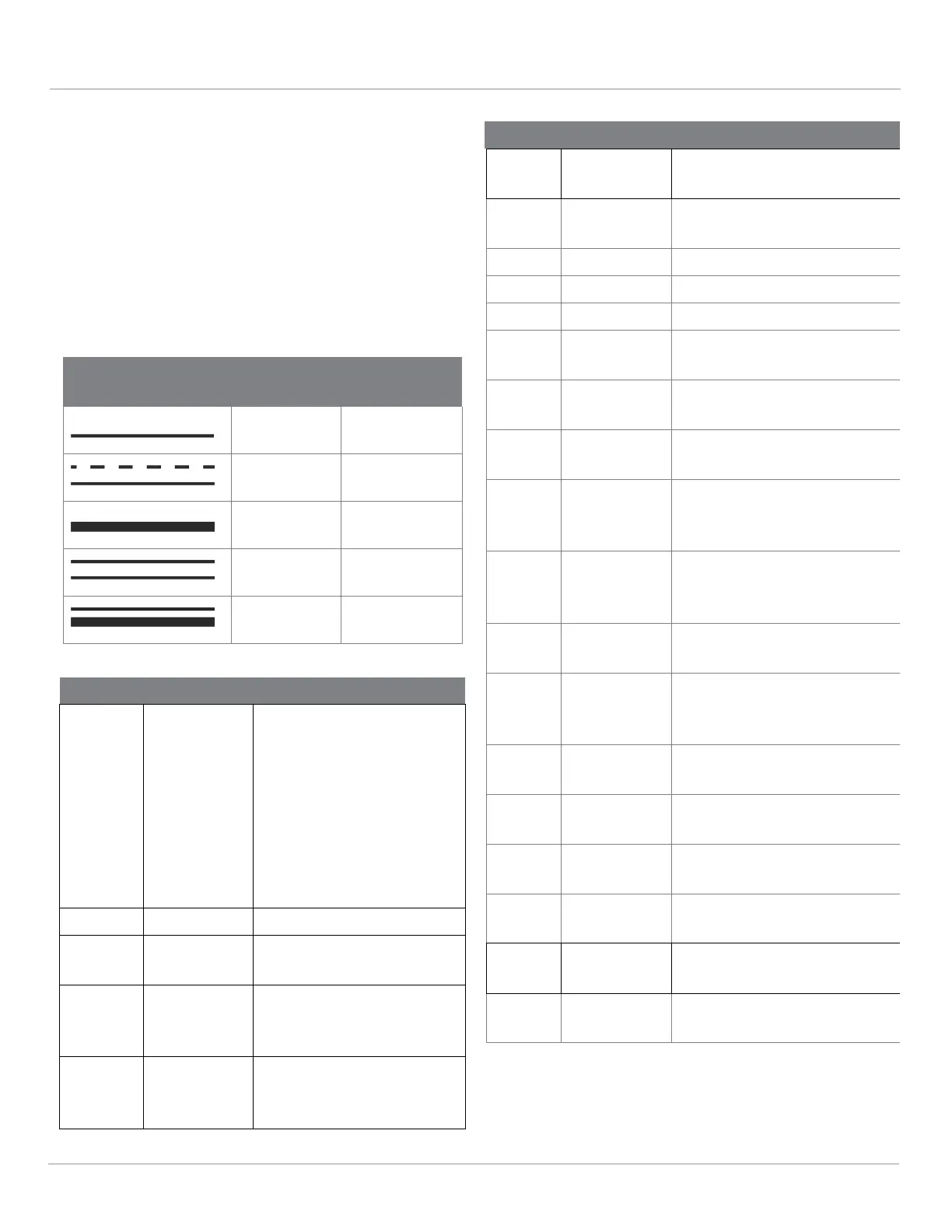
Wiring Diagram Legend
The wiring diagrams show the possible
circuits for the Thermo Top Evo:
System wiring diagram – ON/OFF switch - 31
System wiring diagram for Thermo Top
EVO with SmarTemp 2.0 - page 32
System wiring diagram for Thermo Top
EVO with SmarTemp 3.0 - page 33
System wiring diagram for
TT Evo with an
enclosure box
- page 34
7.5 - 7.5m 15m
Table 1: Cable Cross-Sections
Table 2: Thermo Top Evo Wiring Diagram
Legend
Sensor
ing Pump
Fuse (15A) Mini fuse
Operation In-
dicator Light
Air Fan
Pump
switch or
nector, 10
pin
nector, 2 pin
nector, 4 pin
Overheat sensor and coolant
temperature sensor on item
A2
nector, 2 pin
Circulation pump to control
module
nector, 2 pin
Glow plug to control mod-
ule
nector, 2 pin
Exhaust temperature sensor
to control module
nector, 4 pin
nector, 2 pin
nector, 3 pin
control module engine con-
tact
Timer –
with positive on timer
connection 10: Continuous
operation with immediate
heating
– Timer connection 10
open: Heating duration is
programmable (10 to 120
min.), basic setting 120
ule
perature
Sensor
Temperature
Sensor
coolant circuit

 Loading...


