11 | Electrical Connections
The control element should be installed in a suitable
location on a flat surface if possible, in a visible area.
– Connect control element to existing connect-
ors on heater-unit wiring harness.
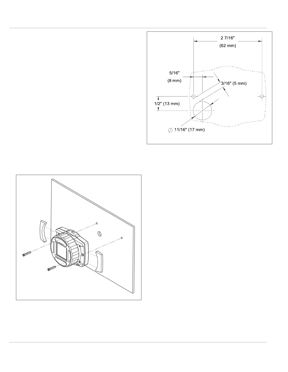
– Use the drilling dimensions to lightly mark the
two mounting holes.
– (Optional Step) To route wire harness through
the mounting surface, drill a 11/16 in (17mm)
hole. Make sure to push harness through the
hole before installing terminals into connector
housing.
– Secure the SmarTemp unit using the two sup-
plied #4 screws.
– Apply the supplied “Heater Off” warning
sticker in a highly visible location to the
driver’s area.
– Observe the installation / operating manual
supplied for proper menu setup.
Fig. 31: SmarTemp Mounting
Fig. 32: SmarTemp Drilling Dimensions (Not to scale)

 Loading...


