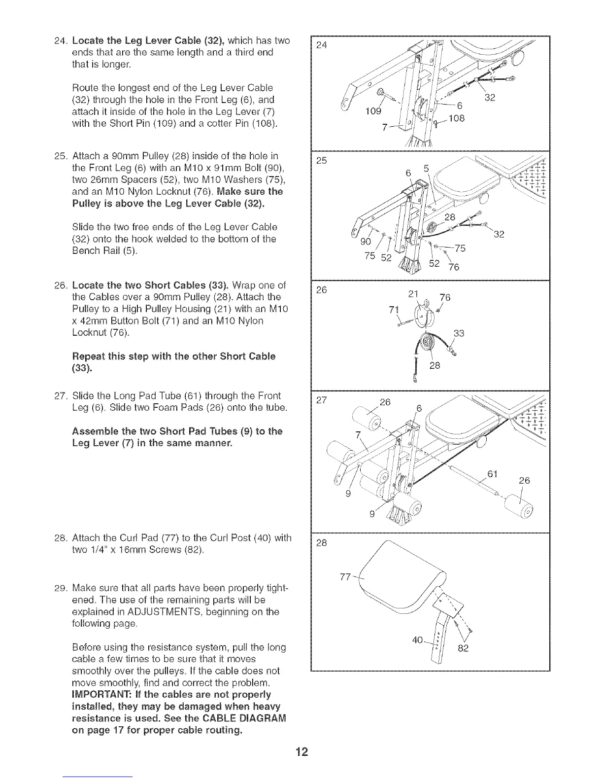
24,Locatethe LegLeverCable(32),whichhastwo
endsthatarethesameUengthanda thirdend
thatislonger,
RoutetheUongestendoftheLegLeverCaMe
(32)throughthehoUeintheFrontLeg(6),and
attachit insideofthehoUeintheLegLever(7)
withtheShortPin(109)anda cotterPin(108),
25,Attacha 90mmPulley(28)insideofthehoUein
theFrontLeg(6)withanMIOx91mmBoUt(90),
two26mmSpacers(52),twoMIOWashers(75),
andanMIONyUonLocknut(76),Makesurethe
Pulleyis abovetheLegLeverCable(32}.
SHdethetwofreeendsoftheLegLeverCaMe
(32)ontothehookweUdedtothebottomof the
BenchRail(5),
26,LocatethetwoShortCables(33}.Wraponeof
theCaMesovera 90mmPulley(28),Attachthe
Pulleytoa HighPulleyHousing(21)withanMIO
x42mmButtonBoUt(71)andanMIONyUon
Locknut(76),
Repeatthis stepwith theotherShortCable
(33}.
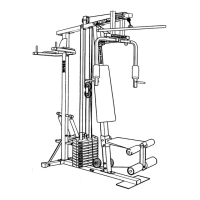
27, SHde the Long Pad Tube (61) through the Front
Leg (6), SHde two Foam Pads (26) onto the tube,
Assemble the two Short Pad Tubes (9} to the
Leg Lever (7} in the same manner.
28, Attach the CurUPad (77) to the CurUPost (40) with
two 1/4" x 16mm Screws (82),
29= Make sure that aH parts have been properly tight-
ened, The use of the remaining parts will be
explained in ADJUSTMENTS, beginning on the
following page,
Before using the resistance system, pull the long
cable a few times to be sure that it moves
smoothly over the pulleys, if the cable does not
move smoothly, find and correct the problem,
iMPORTANT: if the cabJes are not properJy
installed, they may be damaged when heavy
resistance is used. See the CABLE DIAGRAM
on page 17 for proper cabte routing.
24
25
26
27
28
12
32
/
75 52
76
21 76
71
33
28
26
6
40_
82
32
26