This manua! iSdesigned to ensure that the resist-
most PeOPb,However, it iS impo_ant to reanize
that the versatile resistance system has many
parts and that the assembly Process w!Htake
time. Most peopJefind that by setting aside p!enty
d t!me, assembly wi!! go smooth!y:
Before beginning assembly, carefully read the
following information and instructions:
Assembly requires two persons.
Place all parts in a cleared area and remove the
packing materials. Do not dispose of the packing
materials until assembly is completed.
• For help identifying smafl parts, use the PART
IDENTIFICATION CHART, Note: Some small
parts may have been pre-attached for shipping. If
a part is not in the parts bag, check to see if it
has been pre-attached.
Tighten all parts as you assemble them, unless
instructed to do otherwise.
As you assemble the resistance system, make
sure all parts are oriented as shown in the draw-
ings.
The inc!uded AHen wrenches and the follow-
ing tools (not included) are required for assem-
bly:
Two adjustable wrenches
One rubber maltet
One standard screwdriver _.;_
One Phillipsscrewdriver _=C_-_D
Lubricant, such as grease or petroleum jelty,
and soapy water.
Assembly wiii be more convenient if you have a
socket set, a set of open-end or closed-end
wrenches, or a set of ratchet wrenches,
Before beginning assembly, make sure that
you have read and understand the informa-
tion in the box above.
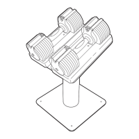
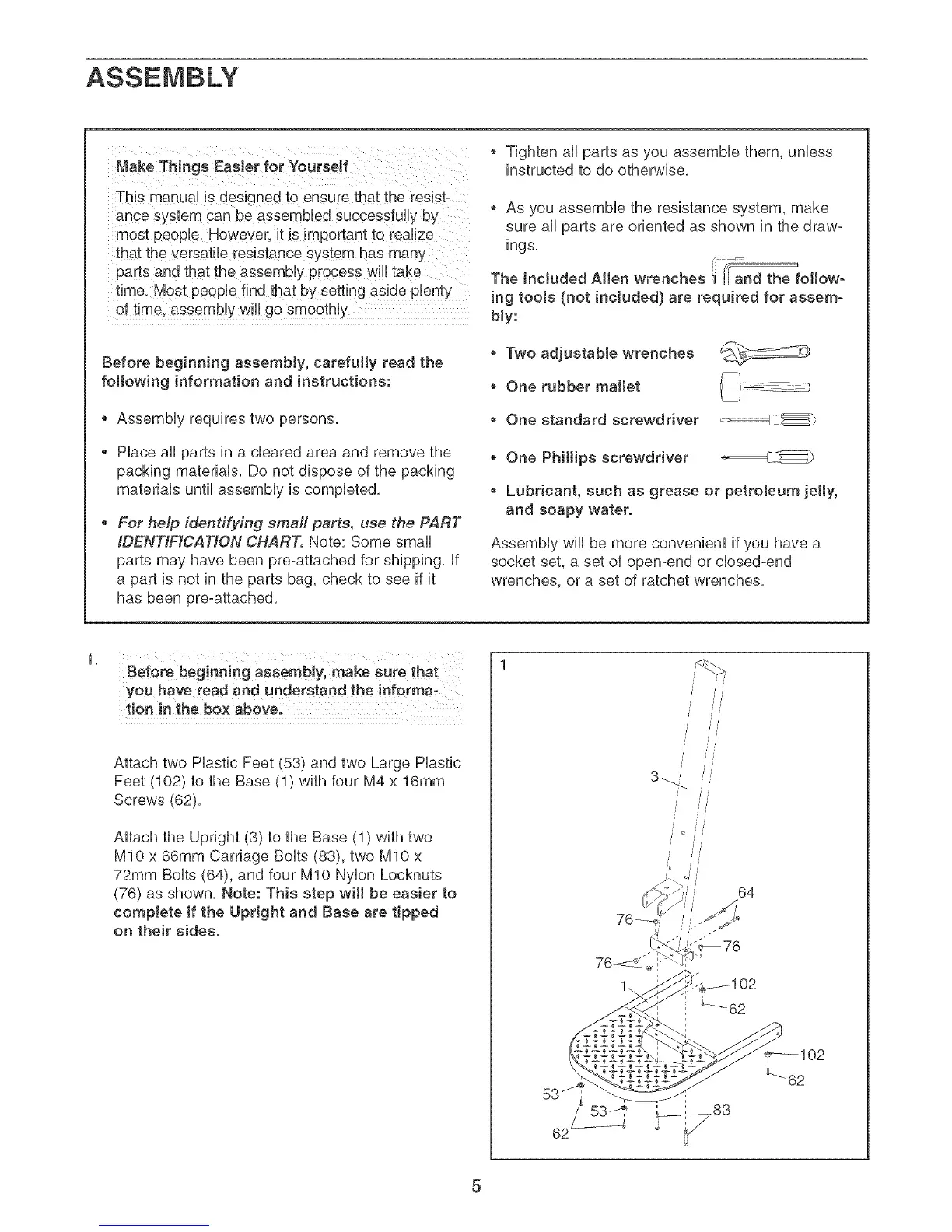
Attach two Plastic Feet r53_ and two Large Plastic
Feet/102/to the Base Ill with four M4 x 16mm
Screws (62/.
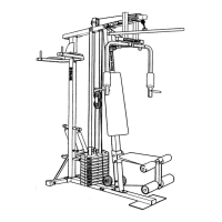
Attach the Upright _3} Io the Base (11 with two
MIO x 66mm Carriage Bolts (83L two MIO x
72mm Bolts (64/. and four MIO Nylon Locknuts
/76 as shown. Note: This step will be easier to
complete if the Upright and Base are tipped
on their sides.
62
53_I _,
/ / /
/// //1//_
64
_102
L
_62