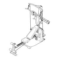
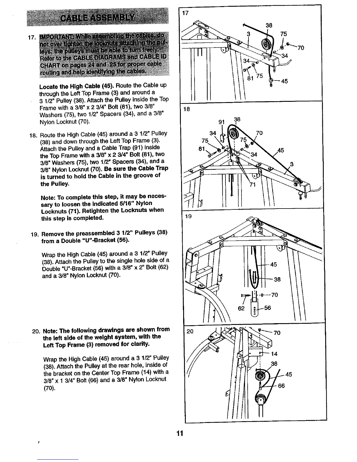
17.
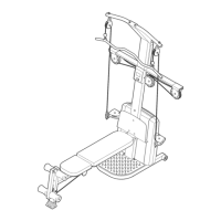
Locate the High Cable (45). Route the Cable up
through the Left Top Frame (3) and around a
3 1/2" Pulley (38), Attach the Pulley inside the Top
Frame with a 3/8" x 2 3/4" Bolt (81), two 3/6"
Washers (75), two 1/2" Spacers (34), and a 3/8"
Nylon Locknut (70).
18. Route the High Cable (45) around a 3 1/2" Pulley
(38) and down through the Left Top Frame (3).
Attach the Pulley and a Cable Trap (91) inside
the Top Frame with a 3/8" x 2 3/4" Bolt (81), two
3/8" Washers (75), two 1/2" Spacers (34), and a
3/8" Nylon Locknut (70). Be sure the Cable Trap
is turned to hold the Cable in the groove of
the Pulley.
Note: To complete this step, it may be neces-
saw to loosen the indicated 5/16" Nylon
Locknuts (71). Retighten the Locknuts when
this step Is completed.
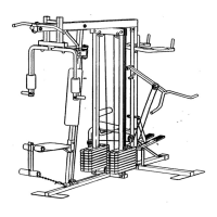
19. Remove the preassembled 3 1/2" Pulleys (38)
from a Double "U"-Bracket (56).
Wrap the High Cable (45) around a 3 1/2" Pulley
(38). Attach the Pulley to the single hole side of a
Double "U"-Bracket (56) with a 3/8" x 2" Bolt (62)
and a 3/8" Nylon Locknut (70).
20. Note: The following drawings are shown from
the left side of the weight system, wfth the
Left Top Frame (3) removed for clarity.
Wrap the High Cable (45) around a 3 112"Pulley
(38). Attach the Pulley at the rear hole, inside of
the bracket on the Center Top Frame (14) with a
3/8" x 1 3/4" Bolt (66) and a 3/8" Nylon Locknut
(70).
75
45
18
91
34
75 \
81,
38
70
19
62
38
11
I