7
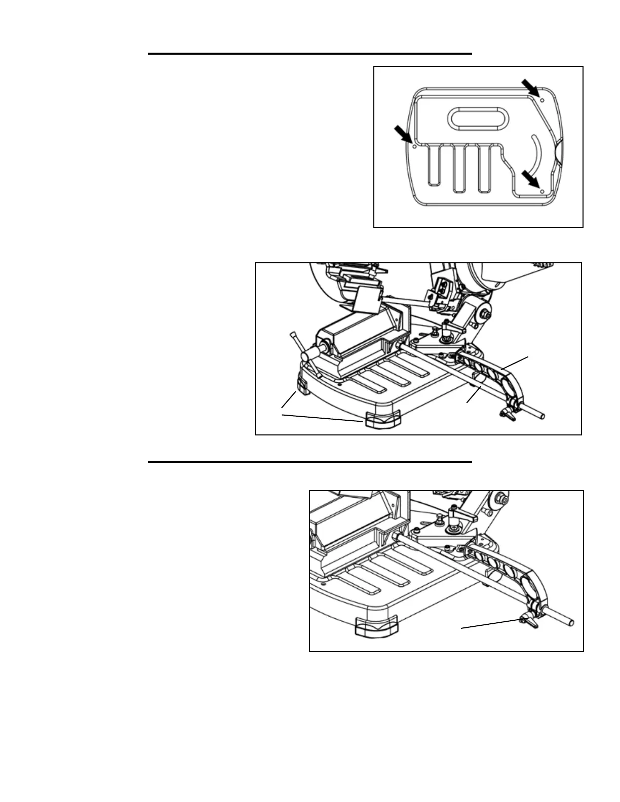
1. Attach the four feet (Fig. B - 1) along each respective corner of
the base.
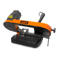
2. Place the machine on a work bench, and secure it in place by us-
ing the three holes provided in the base (Fig. A).
3. Screw the guide rail into the threaded hole on the vise base.
Tighten the nut to fix it. Use an adjustable wrench to turn the hex
nut and fix the guide rail in place.
4. Attach the work stop (Fig. B - 2) to the guide rail (Fig. B - 3).
Secure it in place by tightening the locking handle.
ASSEMBLY
Fig. A
Fig. B
1
3
2
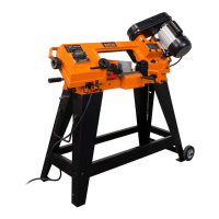
ADJUSTMENTS
If you have to make a series of cuts with a uniform
length, use the supplied work stop.
1. Loosen the lock handle (Fig. C - 1).
2. Slide the work lock to the desired distance.
3. Tighten the lock handle again.
: Make sure that the work stop does not
interfere with the downward movement of the blade.
Fig. C
1
NOTE: the locking handle is spring-
loaded and can be re-positioned as need
be. To re-position the handle, pull it
outwards, turn it to the desired position,
and release it.