18
Installation and Electrical Connection
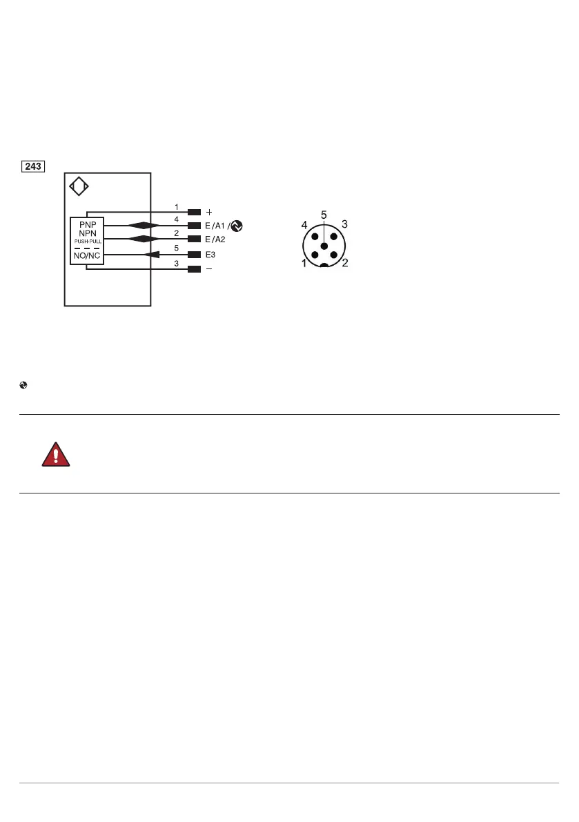
5.2 Electrical Connection
• Wire the sensor in accordance with the connection diagram.
• Switch on the supply voltage (see “3. Technical Data” on page 9).
• The blue supply voltage indicator lights up.
+ supply voltage "+"
− supply voltage "0 V"
O1 switching output 1 normally open (NO)
O2 switching output 2 normally open (NO)
I input (analog or digital)
IO-Link
DANGER!
Risk of personal injury or property damage due to electric current.
Live parts may cause personal injury or damage to equipment.
• The electric device may be connected by appropriately qualified personnel only.
Wire colors:
1 = brown
2 = white
3 = blue
4 = black
5 = gray
 Loading...