22
Setup via IO-Link
8. Setup via IO-Link
The sensors can exchange parameters and process data via IO-Link. The parameters can be used to make
many additional settings on the device. The process data transmit cyclical data and condition monitoring.
To this end, the sensor is connected to a suitable IO-Link master (see product detail page/complementary
products).
The interface protocol and the IODD can be found at www.wenglor.com in the download area for the respec-
tive product.
8.1 Settings via IO-Link/Parameters
8.1.1 Sensor Functions
Function Possible Settings Default
Localization The switching status indicators of the sensor can be switched to flash-
ing. This allows the sensor to be easily located in a plant.
On
LEDs and key illumination flash
Off
LEDs and key illumination function normally
Off
Sensor mode
Normal
The sensor works as a reflex sensor.
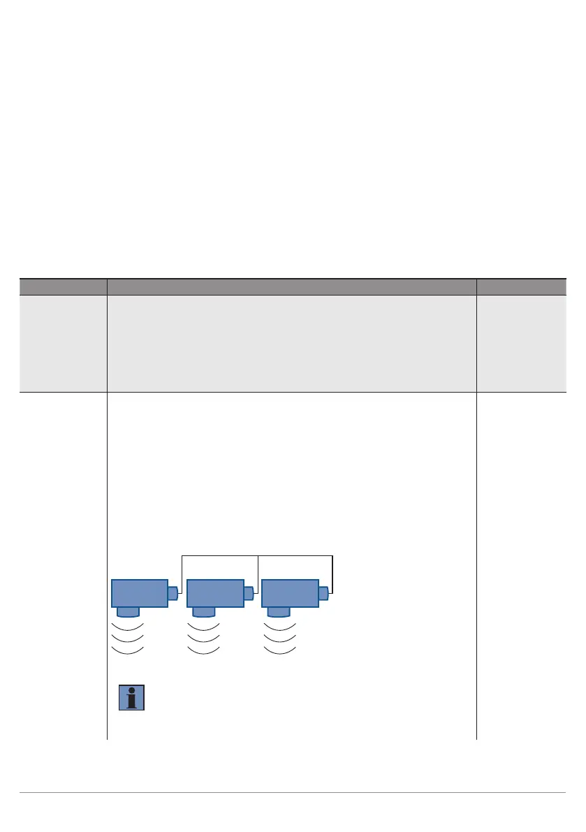
Synchronous Master Unit
Synchronous Sub Unit
A maximum of 40 sensors can be used together in the synchronous
mode in order to detect a large surface. The sensors emit ultrasonic
pulses simultaneously (synchronously).
1. Connect I3/pin 5 of all sensors to each other.
2. Set up one sensor as the "Synchronous Master".
3. Set all other sensors as "Synchronous Sub Unit".
Master Sub Unit 1
SY SY
SY
Sub Unit x
NOTE!
• Synchronous mode is only possible with the PNP output
function.
• In synchronous mode, both outputs O1, O2 can still be
used, as the synchronization runs exclusively via I3.
Normal
 Loading...