19
Ultrasonic Sensors
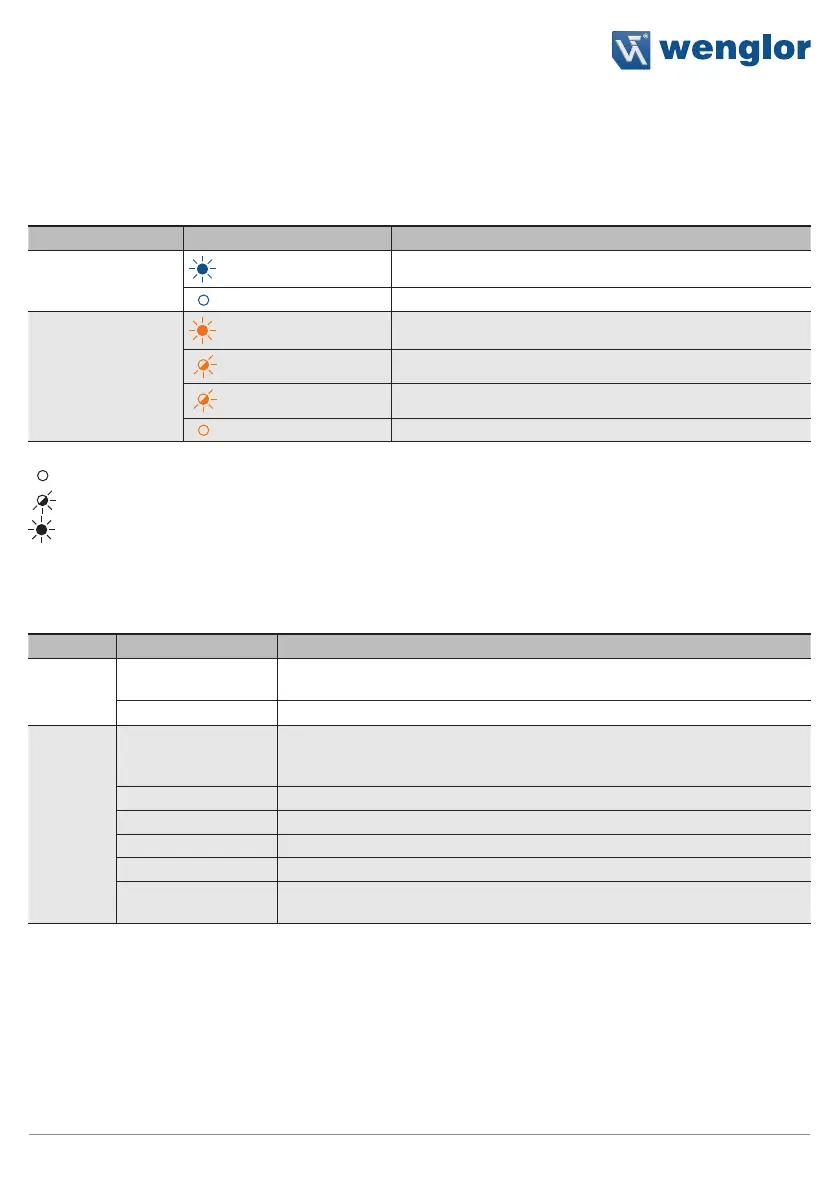
5.3 Diagnosis
5.3.1 LED Indicators
Indicator Status Meaning
Supply voltage
indicator P
Sensor ready for operation
No voltage supply
Switching status
indicator O1, O2
Switching output active
2.5 Hz
Warning
5 Hz
Error
Switching output inactive
Not lit up
Flashing
Permanently lit up
5.3.2 Troubleshooting
Error Possible Cause Elimination
Warning
Warning signal
• Reduce the distance between the sensor and the object
• Adjust the angle to the object
Undervoltage • Increase the voltage supply to at least 18 V DC
Error
No signal
• Adjust sensor object distance
• Minimize environmental influences (air circulation, ultrasonic sources)
• Check installation
Object too close • Increase sensor object distance
Object too far • Decrease sensor object distance
Short circuit • Check the electrical wiring and eliminate the short circuit
Over-temperature • Disconnect the sensor from the supply voltage and allow it to cool
Device error
• Disconnect the sensor from the supply voltage and restart it
• Replace the sensor
Via IO-Link, it is possible to identify the respective causes precisely by means of condition monitoring. Further
diagnosis functions and status messages are also possible. See section “8.2 Condition Monitoring/Process
Data” on page 33.
 Loading...