ENGINE
ADJUSTMENTS
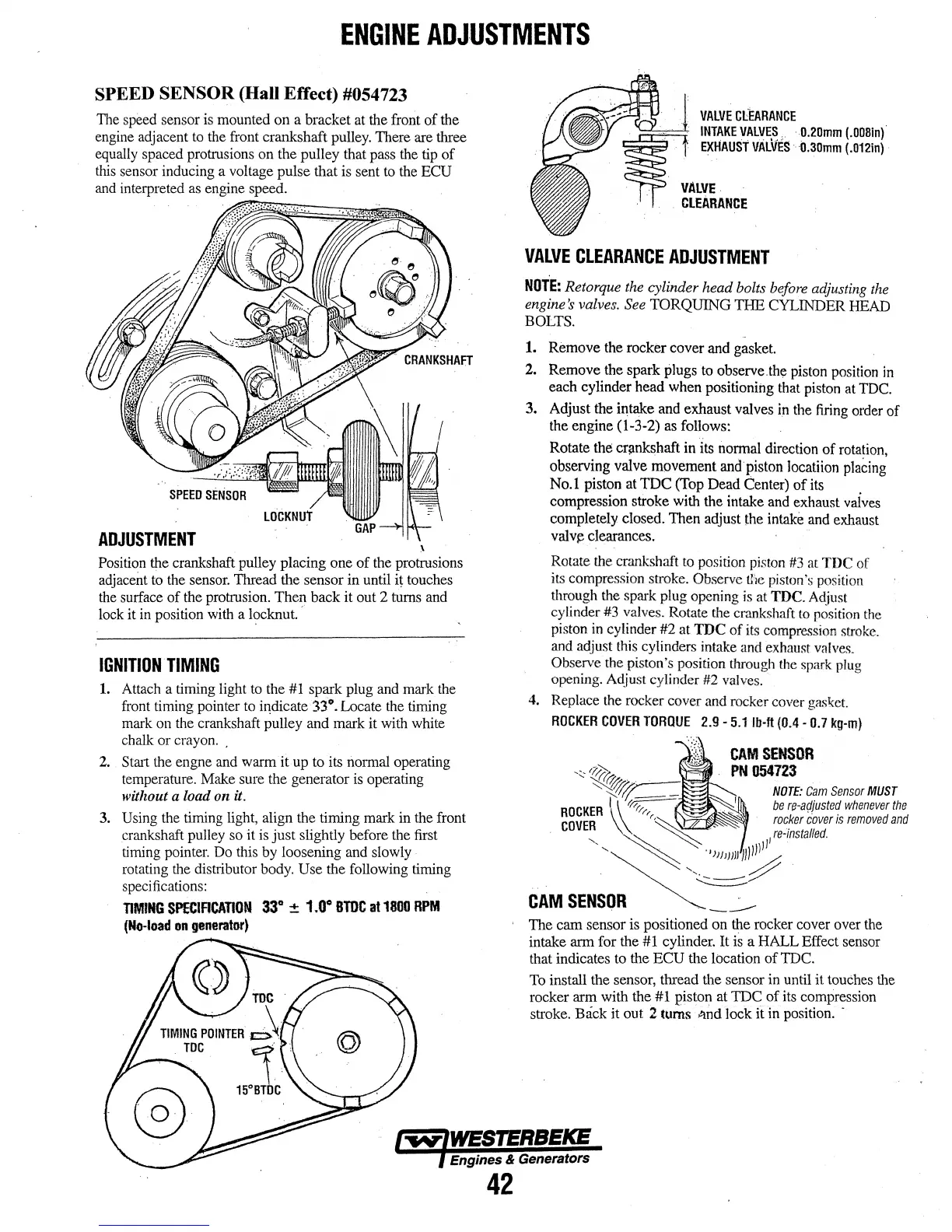
SPEED SENSOR (Hall Effect) #054723
1l1e speed sensor is mounted
on
a bracket at the front
of
the
engine adjacent to the front crankshaft pulley. There are three
equally spaced protrusions on the pulley that pass the tip
of
this sensor inducing a voltage pulse that is sent to the
ECU
and interpreted as engine speed.
LOCKNUT
ADJUSTMENT
\
Position the crankshaft pulley placing one
of
the protrusions
adjacent to the sensor. Tlu·ead the sensor in until
it
touches
the surface
of
the protmsion.
Then
back
it out 2 turns and
lock it in position with a locknut.
c
IGNITION.
TIMING
1.
Attach a timing light to the #1 spark plug and mark the
front timing pointer to
i~dicate
33°. Locate the timing
mark on the crankshaft pulley
and
mark it with white
chalk
or
crayon
..
2.
Strut the engne and warm it up to its normal operating
temperature. Make sure the generator is operating
without a load on
u.
3. Using the timing light, align the timing mark in the front
crankshaft pulley so it
is
just
slightly before the first
timing pointer. Do this by loosening and slowly
rotating the distributor body.
Use the following timing
specifications:
TIMING
SPECIACATION
33"
::!:
1.0"
BTDC
at
1800
RPM
(No-load
on
generator)
VALVE
CLEARANCE
INTAKE
VALVE.~..
·
0.20mm
(.0081n)
EXHAUST
VALVES·
0.30mm
{.012in)
VALVE
CLEARANCE
VALVE
CLEARANCE
ADJUSTMENT
NOTE:
Retorque the cylinder head bolts before adjusting the
engine's valves. See
TORQUING
THE
CYLINDER HEAD
BOLTS.
1.
Remove
the rocker cover
and
gasket.
2. Remove the spark plugs to observe.the piston position
in
each cylinder
head
when positioning that piston at TDC.
3. Adjust the intake and exhaust valves in the firing order
of
the engine (1-3-2) as follows:
Rotate
the cr;mkshaft in its normal direction
of
rotation,
observing valve movement and
piston
locatiion placing
No.1 piston at
TDC
(Top
Dead
Center)
of
its
compression stroke with the intake and exhaust vaives
completely closed.
Then
adjust the intake and exhaust
valv~
clearances.
Rotate the crankshaft to position piston #3
al
TDC
of
its compression stroke. Observe
11\e
piston's position
through the spark plug opening is at
TDC. Adjust
cylinder
#3
valves. Rotate the crankshaft
to
position the
piston in cylinder
#2
at
TDC
of
its compression stroke.
and adjust this cylinders intake and exhaust valves.
Observe the piston's position through the spark plug
opening. Adjust cylinder #2 valves.
4. Replace the rocker cover and rocker cover
gasket.
ROCKER
COVER
TORQUE
2.9-5.1 fll·ft (0.4-
0.7
kg-m)
CAM
SENSOR
PN
054723
NOTE:
Cam
Sensor
MUST
The
cam
sensor is positioned
on
the rocker cover over the
intake arm for the #1 cylinder.
It
is a
HALL
Effect sensor
that indicates to the
ECU
the lbcation
of
TDC.
To install the sensor, tlu·ead the sensor in until
it
touches the
rocker
arm
with the #1 piston at
TDC
of
its compression
stroke.
Back
it out 2 turns
t~nd
lock
it in position. ·
Engines & Generators
42