TESTING
THE
BATTERY
CHARGING
CIRCUIT
THE
CHARGING
SYSTEM
Westerbeke's
low
profile
generators are equipped
with
a
battery
charge
controller that is powered from a separate
winding
in
the
generator.
The
battery charget controller
is
an
encapsulated,
solid-state unit that supplies a DC charging
voltage
to
the generator's starting
batterywhil~.the
generator·
is
operating.
Charging
Voltage: 13.0 - 13.4 Volts
DC
Charging Amperage: 0
-12Amps
DC
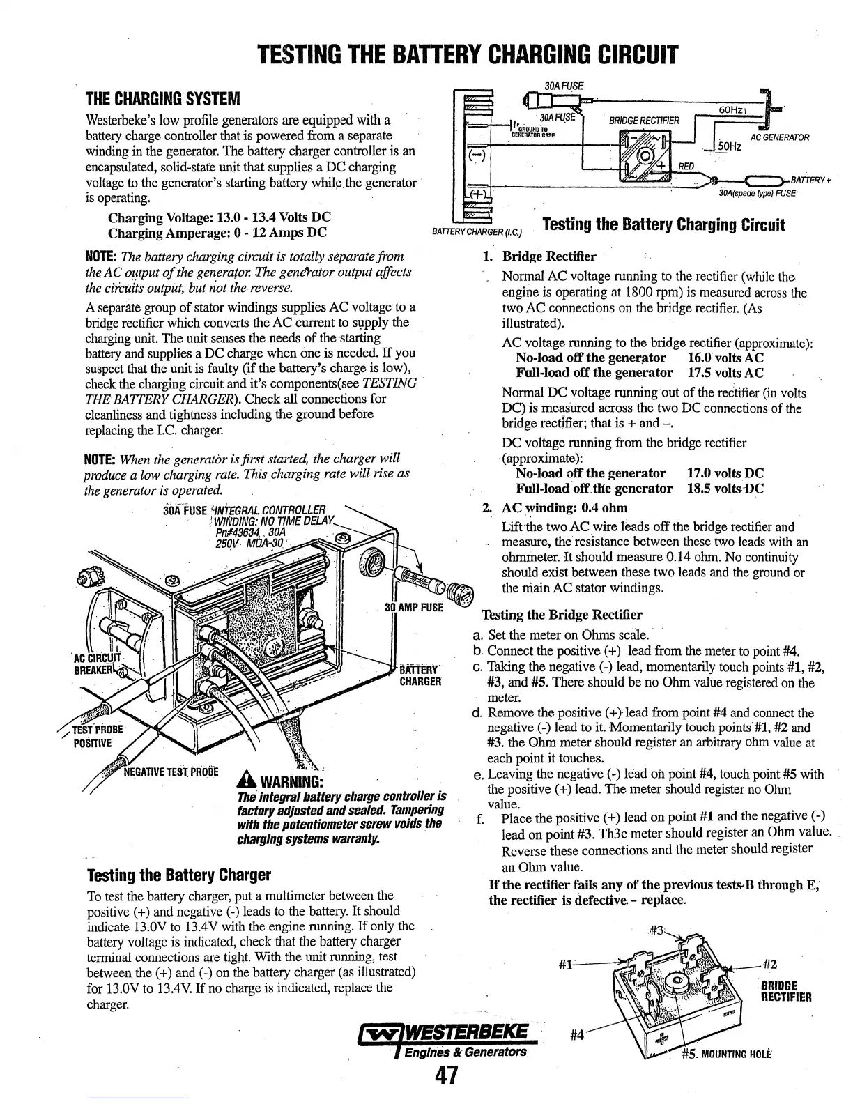
BATTCRYCHARGER(f.C.)
Testing
the
Battery
Charging
Circuit
NOTE:
The
battery
charging
circuit is totally separate from
the.
AC
o~tput
of
the
generator.
The
gene"rator
output affects
the
circuits
output,
but not
the-reverse.
A
sepal.ite
group
of stator windings supplies
AC
voltage
to
a
bridge
rectifier
which
converts
the
AC
current to sppply the
charging
unit.
The unit
senses
the
needs
of the starting
battery
and
supplies
a
DC
charge
when
one
is
needed.
If
you
suspect
that
the unit is
faulty
(if
the battery's charge is low),
check
the
charging circuit
and
it's components(
see
TESTING
THE
BATTERY
CHARGER).
Check all connections for
cleanliness
and
tightness including the ground before
replacing
the
I.C.
charger.
NOTE:
lVhen
the
generator
is
first
started,
the
charger will
produce
a
low
charging
rate.
This.
charging
rate
will rise as
the
generator
is
operated.
3o.fFUSE
,,-;,
uTrr.!a/lt
.,,...,I'TTJ,,
..
I
Wtli61N~t~JJ
~
f?IJ!1§6~
A
wARNING:'
The.
Integral
battery
charge
controller
is
factory
adjusted
and
sealed.
Tampering
with
the
potentiomBtBr
scrBw
voids
.the
charging
systems
warranty.
Testing
the
Battery
Charger
To
test
the battery
charger,
put a multimeter between the
positive (
+)
and
negative
(-)
leads
to
the
battery.
It should
indicate
13.0V
to
13.4V
with
the
engine
running.
If
only
the
battery
voltage
is
indicated, check that the battery charger
tenninal connections
are
tight.
With
the unit
running.
test
between the(+) and(·)
on
the
battery charger
(as
illustrated)
for
13.0V
to
13.4V.
If
no
charge
is indicated, replace
the
charger.
1.
Bridge Rectifier
Normal
AC
voltage running
to
the
rectifier
(while
the
engine
is
operating at
1800
rpm)
is
measured
across
the
two
AC
connections
on
the bridge
rectifier.
(As
illustrated).
AC
voltage running
to
the bridge rectifier
(approximate):
No-load
off
the
gener~tor
16.0 volts AC
Full-load
off
the
generator
17.5 volts AC
Normal DC voltage running·out
of
the
reetifier
(in
volts
DC)
is
meas'ured
across the
two
DC
connections
of
the
bridge
rect{fier;
that
is
+
and
-.
DC voltage running
from
the bridge rectifier
·(approximate):
No-load
otT
the
generator
17.0 volts DC
Full-load.off.tlie
generator
18.5
volts-D~
2.
AC
\Vinding: 0.4 ohm
Liftthe two AC wire
leads off
the
bridge
rectifier
and
measure, the resistance between
these
two
leads
with
an
ohmmeter.
It
should measure 0.14
ohm.
No
continuitv
should exist between these
two
leads
and
the
ground
~r
the main
AC
stator windings.
Testing
the
Bridge
Rectifier
a. Set the meter
on
Ohms
sca1e.
·
b.
Connect the positive (
+)
lead from
the
meter
to
point
#4.
c.
Taking
the
negative
(-)
lead, momentarily
touch
points
#1,
#2,
#3,
and #5. There should be
no
Ohm
value
registered
on
the
meter.
d.
Remove
the
positive (+}lead
from
point
#4
and
connect
the
negative.(-) lead
to
it.
Momentarily
touch
points'#l, #2
and
#3.
the
Ohm
meter should register
an
arbitrary
ohm
value
at
each point it touches. ·
e. Leaving the negative
(-)
lead
oil
point
#4,
touch
point
#5
with
the
positive (+)lead. The meter should register
no
Ohm
value.
··
, f. Place the positive ( +) lead on point #1
and
the negative (-)
lead on point #3. Th3e meter should register
an
Ohm
value. .
Reverse these connections and the meter should register
an
Ohm value.
If
the
rectifier falls any
of
the
previous test&B through
E;
the
rectifier' is defective.- replace.
#2
.BRIDGE
RECTIFIER
l"'MTIWESTERBEKE
#4.
· f
Engln'es
&
GeneratQrs
47