BC
GENERATOR
SINGLE
PHASE
GENERATOR
OUTPUT
To
confirm the generator's output capacity,
run
the
generator first with no-load, then at half capacity, and
finally
load it to full capacity (indicated on the
generators data plate).
Voltage
and load can be
monitored using a portable meter and amp probe.
The output should be checked periodically to ensure
proper operation
of
the generator and
the
appliances
it
supplies.
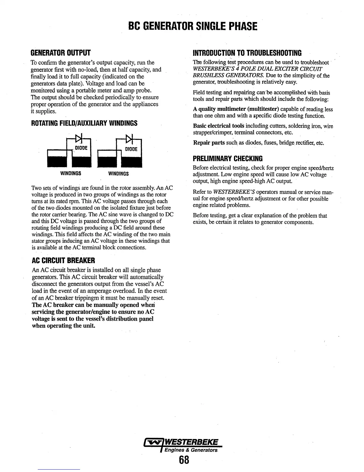
ROTATING
FIELD/AUXILIARY
WINDINGS
WINDINGS
WINDINGS
'I\vo
sets
of
windingS
are
found
in
the
rotor
assembly.
An AC
voltage
is
produced
in
two
groups
of
windings
as
the
rotor
turns
at
its
rated
rpm.
This
AC
voltage
passes
through
each
of
the
two
diodes
mounted
on
the
isolated
fixture
just
before
the
rotor
carrier
bearing.
The
AC
sine
wave
is
changed
to
DC
and
this
DC
voltage
is
passed
through
the
two
groups
of
rotating
field
windings
producing
a
DC
field
around
these
windings.
This
field
affects
the
AC
winding
of
the
two
main
stator
groups
inducing
an
AC
voltage
in
these
windings
that
is
available
at
the AC
terminal
block
connections.
AC
CIRCUIT
BREAKER
An
AC
circuit breaker
is
installed on all single phase
generators. This
AC
circuit breaker will automatically
disconnect the generators output from the vessel's AC
load
in
the event
of
an amperage overload. In the event
of
an
AC
breaker trippingm
it
must
be
manually reset.
The AC breaker
can
be manuaUy opened wheri
servicing
the generator/engine to ensure no AC
voltage
is
sent to the vessel's distribution panel
when operating the
unit.
68
INTRODUCTION
TO
TROUBLESHOOTING
·-
The
following.
teSt
procedures ctm be
us~
to
troubleshoot·
WESTERBEKE:'S
4 POLE DUAL EXCITER CIRCUIT
BRUSHLESS GENERATORS. Due
to
the
simplicity
of.
the
generator,
troubleshooting
i~
relatively
easy.
·
Field testing
and
repairing can'be accomplished
With
basis
tools
and
repair parts
which,
siJould
include
the
following:
A quality multimeter (mul,titester) capable ofreading
less
than
one
ohm and with a ipecific
diode
testing
function.
Basic electrlcal
toolS
blcludin~
cutters, soldering
iron,
wire
strapPer/crimper,
terminal connectors, etc. . ·
Repair parts such
as
diodes, fuses,
bridge.
rectifier,
etc.
PRELIMINARY
CHECKING
Before
electrical
testing,
check
for
proper
engine
speed/hertz
adjustment
Low
engine
speed
will
cause
low
AC
voltage
output,
high
engine speed-high AC
output.
Refer
to
.WESTERBEKE'S
operators
manual
or
service
man-
ual
for
engine.
speed/hertz
adjustment
or
for
other
possible
engine
related
problems.
Before
testing,
get a clear explanation of
the
problem
that
exists,
be
certain it relates
to
generator
components.
 Loading...