BC
GENERATOR
SINGLE
PHASE
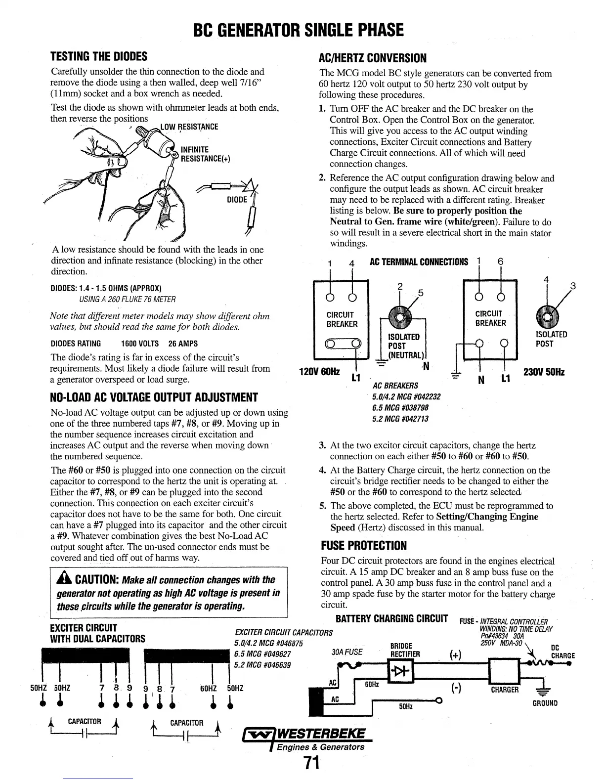
TESTING
THE
DIODES
Carefully unsolder
the
thin
connection to
the
diode
and
remove the diode using a
then
walled, deep well7/16"
(llmm)
socket
and
a
box
wrench
as
needed.
Test
the
diode
as
shown
with
ohmmeter leads at
both
ends,
then
re~erse
the positions
A
low
resistance should be found with the leads
in
one
direction
and
infinate resistance (blocking)
in
the other
direction.
DIODES:
1.4-
1.5
OHMS
(APPROX)
USING
A
260
FLUKE
76
METER
Note
that different meter models
may
show different ohm
values,
but should
read
the
same
for both
diodes.
DIODES
RATING
1600
VOLTS
26
AMPS
The diode's rating
is
far
in
excess of the circuit's
requirements. Most
likely
a diode failure will result
from
a generator overspeed
or
load
surge.
NO·LOAD
AC
VOLTAGE
OUTPUT
ADJUSTMENT
No-load
AC
voltage
output
can
be adjusted
up
or
down
using
one
of
the
three numbered
taps
#7,
#8,
or
#9.
Moving
up
in
the
number sequence increases circuit excitation
and
increases
AC
output
and
the
reverse when moving
down
·
the
numbered
sequence.
The
#60 or
#50
is
plugged
into
one connection
on
the
circuit
capacitor
to
correspond
to
the
hertz the unit
is
operating
at.
Either
the
#7,
#8,
or
#9
can
be
plugged into
the
second
connection. This connection
on
each exciter circuit's
capacitor
does
not
have
to
be the same for
both.
One
circuit
can
have
a #7 plugged into
its
capacitor
and
the
other circuit
a
#9.
Whatever combination gives
the
best No-Load
AC
output sought
after.
The un-used connector
ends
must
be
covered
and
tied off.out of harms
way.
A
CAUTION:
Make
all
connection
changes
with
the
generator
not
operating
as
high
AC
voltage
is
present
in
these
.circuits
while
the
generator
is
operating.
AC/HERTZ
CONVERSION
The
MCG
model
BC
style generators
can
be converted
from
60
hertz
120
volt output
to
50 hertz
230
volt output
by
following
these procedures.
1.
Tum
OFF
the
AC
breaker
and
the
DC
breaker
on
the
Control
Box.
Open
the
Control Box
on
the
generator.
This
will
give
you
access
to
the
AC
output
winding
connections, Exciter Circuit connections
and
Battery
Charge Circuit connections.
All
of
which
will
need
connection
changes.
2.
Reference
the
AC
output configuration
drawing
below
and
configure
the
output leads
as
shown.
AC
circuit breaker
may
need
to
be
replaced with a different
rating.
Breaker
listing
is
below.
Be
sure to properly position the
Neutral to Gen. frame wire (white/green). Failure
to
do
so
will result
in
a severe electrical short
in
the
main
stator
windings.
1
4
AC
TERMINAL
CONNECTIONS
1
6
CIRCUIT
BREAKER
2
CIRCUIT
BREAKER
ISOLATED
POST
120V60Hz
L1
230V50Hz
AC
BREAKERS
5.0/4.2
MCG
#042232
6.5
MCG
#038798
5.2
MCG
#042713
3.
At
the
two excitor circuit capacitors,
change
the
hertz
connection
on
each
either #50
to
#60
or #60 to
#50.
4.
At
the
Battery
Charge
circuit, the hertz connection
on
the
circuit's bridge rectifier
needs
to
be
changed
to
either
the
#50
or
the
#60
to
correspond
to
the
hertz selected
5.
The above completed, the
ECU
must
be reprogrammed
to
the
hertz selected. Refer
to
Setting/Changing Engine
Speed (Hertz) discussed
in
this
manual.
FUSE
PROTECTION
Four
DC
circuit protectors are
found
in
the
engines
electrical
circuit. A
15
amp
DC
breaker
and
an
8
amp
buss
fuse
on
the
control panel. A
30
amp
buss
fuse
in
the
control panel
and
a
30
amp
spade
fuse
by
the
starter motor
for
the
battery charge
circuit.
BATTERY
CHARGING
CIRCUIT
EXCITER
CIRCUIT
WITH
DUAL
CAPACITORS
EXCITER
CIRCUIT
CAPACITORS
5.0/4.2
MCG
#046875
~
6.5MCG#049627
~
I I . l . . 1 J
5.2
MCG
#046639
FUSE·
INTEGRAL
CONTROLLER
WfNDfNG:
NO
TtME
DELAY
Pn/43634
30A
250V
MDA-30
50HZ
60HZ
• •
7
8.
9
•••
9 \
s.·
7
60HZ
50HZ
• • • • •
(·)
50Hz
Engines & Generators
71