RAW
WATER
PUMP
(PN.042026)
PUMP
OVERHAUL
111NNER
BEARING
21
,
16sPACER
OUTER
BEARING
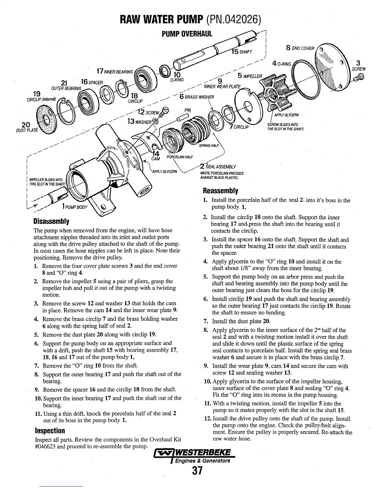
Disassembly
The
pump
when
removed from the engine, will
have
hose
attachment
nipples
threaded into its inlet and outlet ports
along
with
the
drive
pulley
attached
to
the
shaft of the
pump.
In
most
cases
the hose nipples can be left
in
place. Note their
positioning.
Remove
the
drive
pulley.
1.
Remove
the four cover plate screws 3
and
the end cover
8
and
"0"
ring
4.
2.
Remove
the
impeller 5 using a pair of pliers,
grasp
the
impeller
hub
and pull it out of
the
pump
with
a twisting
motion.
3.
Remove
the
screw
12
and washer 13 that holds
the
cam
in
place.
Remove
the
cam 14 and
the
inner wear plate
9:
4.
Remove
the
brass circlip 7 and
the
brass holding washer
6
along
with
the
spring half
of
seal 2. ·
5.
Remove
the dust plate 20 along
with
circlip 19.
6.
Support
the
pump
body on
an
appropriate surface
and
with
a
drift,
push
the
shaft 15
with
bearing assembly 17,
18,
16
and
17 out of the pump
bodyl.
7.
Remove
the
"0''
ring 10 from
the
shaft.
8.
Support
the
outer bearing 17
and
push
the
shaft.
out of
the
bearing.
9.
Remove
the
spacer 16
and
the circlip 18 from the
shaft.
10.
Support
the
inner bearing 17
and
push the shaft out of the
bearing.
11.
Using
a
thin
drift, knock
the
porcelain half of
the
seal
2
out
of
its
boss
in
the
pump body
·1.
Inspection
Inspect
all
parts.
Review
the
components
in
the Overhaul
Kit
#046623
and
proceed
to
re-assemble
the
pump.
Reassembly
1.
Install the porcelain half of the
seal
2:
into
it's
boss
in
the
pump
body
1.
2.
Install the circlip 18 onto.the shaft. Support
the
inner
bearing
17 andpress the shaft into
the
bearing
until
it
contacts
the
circlip ..
3. Install the spacer 16 onto the shaft. Support
the
shaft
and
push
the
outet bearing 21 onto
the
shaft
until
it
contacts
the
spacer.
4.
Apply
glycerin
to
the
"0"
ring 10 and install
it
on
the
shaft about
118"
away
from the inner
bearing.
5. Support the pump body
on
an
arbor press
and
push
the
shaft and bearing assembly into the pump
body
until
the
outer bearing just clears the boss for the circlip 19.
6.
Install circllp 19 and push the shaft
and
bearing
assembly
so
th~
outer bearing 17 just contacts
the
circlip 19.
Rotate
·
the
sl'iaft
to
ensure no binding.
7. Install the dust plate 20.
8.
Apply glycerin
to
the inner surface of
the
2m1
half of
the
seal 2
and
with a twisting motion install it over
the
shaft
and
slide it down. until the plastic surface of
the
spring
seal
contacts
to
porcelain half. Install the
spring
seal
brass
wash~r
6 and secure it
in
place with the brass circlip
7.
9. Install
the
wear plate 9, cam 14
and
secure
the
cam
with
screw 12 and sealing washer
13.
10. Apply glycerin
to
the surface of
the
impeller
housing,
inner surface of the cover plate 8
and
sealing
"0"
ring
4.
Fit the
"0"
ring into its recess
in
the
pump
housing.
11.
With
a twisting motion, install
the
impeller 5
into
the
pump
so
it mates properly with
the
slot
in
the
shaft
15.
12. Install
the
drive pulley onto the shaft of
the
pump.
Install
the
pump onto the engine. Check
the
ptilley/belt
align-
ment.
Ensure the pulley
is
properly
secured.
Re-attach
the
raw
water hose.
Engines & Generators
37
 Loading...