COMPONENT
TESTING
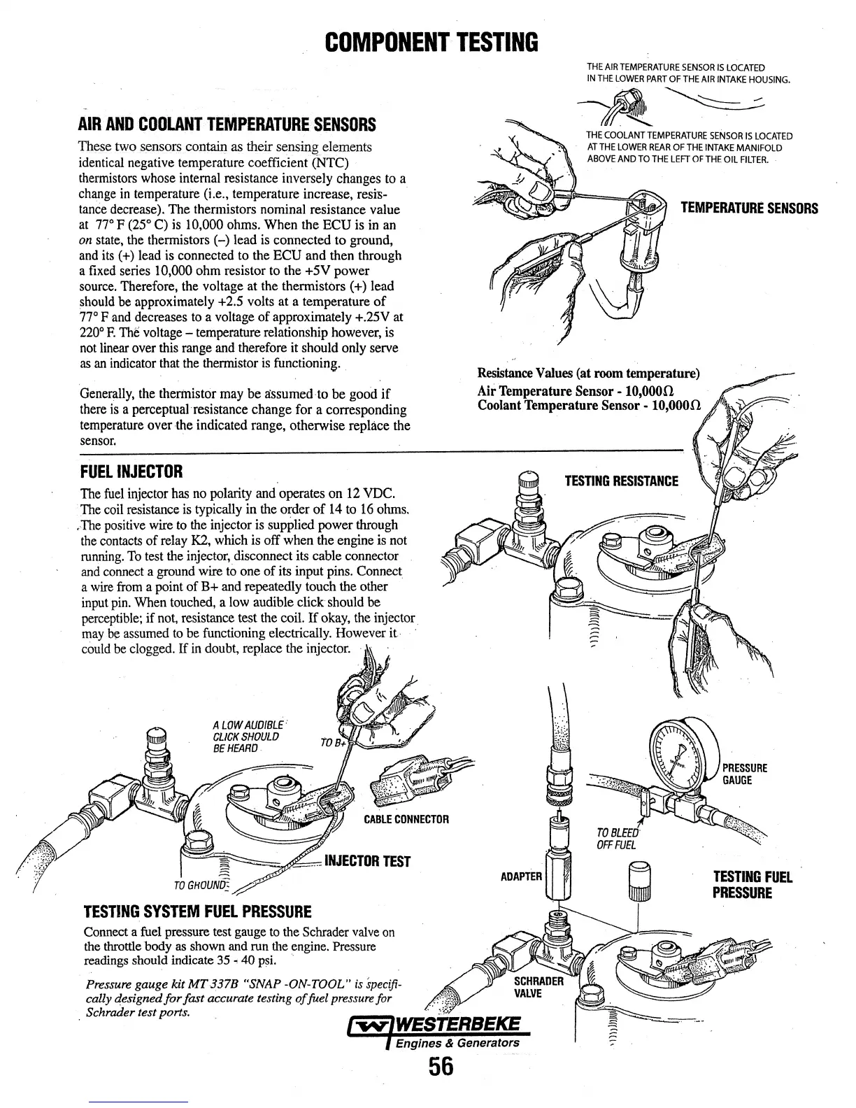
AIR
AND
COOLANT
TEMPERATURE
SENSORS
Th~e
two sensors
con~
as
their sensing.elements
identical
negative temperature coefficient (NrC)
thermistors
whose
internal
resistance inversely changes
to
a
change
in
temperature (i.e., temperature increase,
resi'S-
·
tance
decrease).
The thennistors nominal resistance value
at
no
F
(25°
C)
is
10,000
ohms.
When the ECU is
in
an
on
state,
the
thennistors (-) lead
is
connected
to
ground,
and
its
( +) lead
is
connected
to
the
ECU
and then through
a
fixed
series 10,000
ohm
resistor
to
the +5V power
source.
Therefore, the voltage
at
the
thennistors ( +) lead
should
be
approximately
+2.5
volts at a temperature of
no
F
and
decreases
to
a
voltage
of approximately
+.25V
at
220°
F.
The
voltage
- temperature relationship
however,
is
not
linear
over
this
range
and
therefore it should only
serve
as
an
indicator
that
the
thermistor
is
functioning.
Generally,
the
thermistor
may
be
a:ssumed·to
be good
if
there
is
a perceptual· resistance change for a corresponding
temperature
over
-the
indicated range, otherwise replace the
sensor.
FUEL
INJECTOR
The
fuel
injector
has
no
polarity
and
operates on
12
VDC.
The
coil
resistance
is
typically in
the
order of
14
to
16
ohms
.
..
The
positive
wire
to
the
injector
is
supplied power
through
the
contacts
of
relay
K2,
which
is
off
when
the
engine
is
not
running.
To
test
the
injector,
disconnect its cable connector
and
connect
a
ground
wire
to
one of
its
input
pins.
Connect
a
wire
from
a
point
of B+
and
repeatedly touch the other
input
pin.
When
touched,
a
low
audible click should be
perceptible;
if
not,
resistance test
the
coil. If
okay,
the
injector.
may
be
assumed
to
be
functioning electrically.
However
it
·
could
be
clogged.
If
in
doubt,
replace
the
injector.
A
LOW
AUDIBLE:
CLICK
SHOULD
BE
HEARD.
TESTING
SYSTEM
FUEL
PRESSURE
Connect
a
fuel
pressure
test
gauge
to
the
Schrader
valve
on
the
throttle
body
as
shown
and
run
the
engine.
Pressure
readings
should
indicate
35
•
40
psi.
·.
Pressure gauge
kit
MT337B
"SNAP -ON-TOOL"
is
specifi-
cally d,esigned
for
fast
accurate testing
of
fuel pressure for
. Schrader test ports.
56
THE
AIR
TEMPERATURE
SENSOR
IS
LOCATED
IN
THE
LOWER
PART
OF
THE
AIR
INTAKE
HOUSING.
~~
THE
COOLANT
TEMPERATURE
SENSOR
IS
LOCATED
AT
THE
LOWER
REAR
OF
THE
INTAKE
MANIFOLD
ABOVE
AND
TO
THE
LEFT
OF
THE
OIL
FILTER.
TEMPERATURE
SENSORS
Resistance
Values
(at
room
temperature)
Air
Temperature
Sensor
-
to,ooon
Coolant
Temperature Sensor -
to,ooon
TESnNG
RESISTANCE
TESTING
FUEL
PRESSURE
 Loading...