COMPONENT
TESTING
TESTING
THE
OIL
PRESSURE
SENSOR
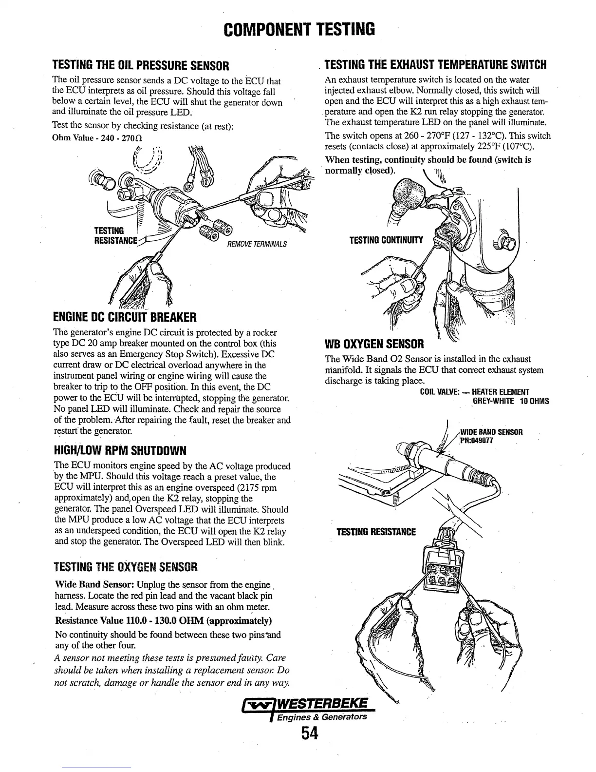
The oil pressure sensor sends a DC voltage
to
the
ECU
that
the
ECU interprets
as
oil pressure. Should
this
voltage
fall
below a certain level, the ECU will shut the generator
down
and
illuminate the oil pressure LED:
Test
the sensor
by
checking resistance (at
rest):
Ohm Value· 240-
2700
ENGINE
DC
CIRCUIT
BREAKER
The generator's engine
DC
circuit is protected
by
a rocker
type
DC
20
amp
~reaker
mounted on the control box
(this
also serves
as
an
Emergency Stop Switch). Excessive
DC
current draw or
DC
electrical overload anywhere
in
the
instrument panel wiring or engine wiring will cause
the
breaker
to
trip to the OFF
po~ition.
In this
event,
the
DC
power
to
the ECU
will
be intenilpted, stopping
the
generator.
No
panel LED will illuminate. Check and repair
the
source
of
the
problem. Mter repairing the fault, reset
the
breaker
and
restart·
the
generator.
HIGH/LOW
RPM
SHUTDOWN
The ECU monitors engine speed
by
the
AC
voltage produced
by
the MPU. Should
this
voltage reach a preset value,
the
ECU
will interpret
this
as
an
engine overspeed
(2175
rpm
approximately)
ancJ.,open
the
K2
relay, stopping the
generator.
The panel Overspeed LED will illuminate. Should
the
MPU
produce a
low
AC voltage that
the
ECU
interprets
as
an
underspeed condition, the ECU will open
the
K2
relay
and stop
the
generator. The Overspeed LED will
then
blink.
TESTING
THE
OXYGEN
SENSOR
Wide Band Sensor: Unplug the
s_ensor
from the engine .
harness. Locate
Ute
red
pin
lead and the vacant black
pin
le~d.
Measure across these
two
pins with an ohm
~eter.
Resistance Value 110.0 - 130.0
OHM
(approximately)
No
continuity should
be
found between these
two
pins-and
any
of
the
other
four.
A sensor not meeting
these
tests
is
presumed faulty.
Care
should
be
taken
when
installing a replacement
sensor.
Do
not
scratch,
damage
or handle the sensor end
in
any
way.
.
TESTING
THE
EXHAUST
TEMPERATURE
SWITCH
An
exhaust temperature switch is located
on
the
water
injected exhaust
elbow.
Normally
closed,
this
switch
will
open and the ECU will interpret
this
as
a
high
exhaust
tern-
. perature and open
the
K2 run
relay
stopping
the
generator.
The exhaust temperature LED
on
the
panel
will
illuminate.
The switch opens
at
260-
270°F (127-
132°C}.
This
switch
resets (contacts close) at approximately
225°F
(l07°C}.
When testing,.continuity should be found (switch is
· normally closed). ·
'1\t\~
WB
OXYGEN
SENSOR
The Wide Band
02
Sensor is installed in
the
exhaust
manifold. It signals the ECU that correct exhaust
system
discharge is taking place.
TESTING
RESISTANCE
COIL
VALVE:
-
HEATER
ELEMENT
GREY·WHITE
10
OHMS
J
,WIDE
BAND
SENSOR
/J
.'PM:049077
.
Engines & Generators
54