COMPONENT
STATIC
TESTING
GENERAL
All
DC
voltage measurements
are
made
to
the engine
battery
negative
ground
point unless specified otherwise. In making
test measurements, make sure that a good ground
for
the
meter
is
established, preferably
the
point where
the
negative
battery
is
connected
to
the
engine. Battery positive voltage
is
indicated
as
B+
and
should measure
no
less
than
11.5
volts.
AC
voltage measurements should be made with a
true
RMS .
AC
meter
to insure accuracy .
.
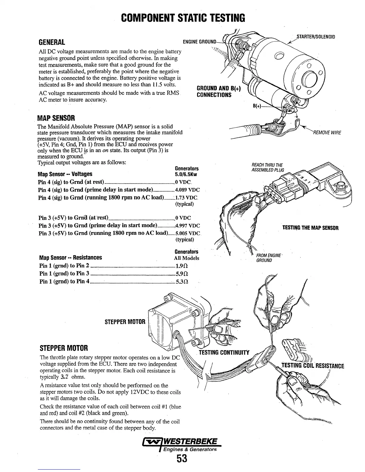
MAP
SENSOR
The
Manifold Absolute Pressure (MAP) sensor is a solid
state pressure transducer which measures the
intake manifold
pressure
(vacuum).
It derives its operating power
(+5V,
Pin
4;
Gnd,
Pin
1)
from
the
ECU
and
receives power
only
when
the
ECU
~
in
an
on
state. Its output
(Pin
3)
is
measured
to
ground.
Typical
output
voltages
are
as
follows:
GROUND
AND
B(+)
CONNECTIONS
Generators
Map
Sensor
--
Voltages
5.D/6.5Kw
Pin 4
(sig)
to
Gmd
(at rest) 0
VDC.
Pin 4 (sig) to
Gmd
(prime delay in
start
mode)
4.089
VDC
Pin 4 (sig) to Grnd (running 1800
rpm
no AC
load)_'
1.73
VDC.
(typical)
Pin 3
(+5V)
to Grn1l (ati·est) . 0
VDC
Pin 3
(+5V)
to
Grnd
{prime delay in
start
mode)
4.997
VDC
Pin 3
(+SV)
to
Grnd
(running 1800
rpm
noAC
load)_5,005 VDC.
(typical)
Generators
Map
Sensor
--
Resistances
AU
Models
Pin 1 (grnd)
to
Pin
2----------1.90
Pin 1 (grnd) to Pin 3 5.9fi
Pin 1 (gmd)
to
Pin
4
_________
__;_;_·
·
5.30
STEPPER
MOTOR
STEPPER
MOTOR
The
throttle
plate
rotary
stepper motor operates on a
low
DC
voltage
supplied
from
the
ECU.
There are two independent
operating
coils
in
the
stepper
motor.
Each coil resistance
is
typically
3.i
ohms.
A
resistance
value
test only should
be.
performed
on
the
stepper
motors
two
coils.
Do
not apply 12VDC to these coils
as
it
will
damage
the
coils.
Check
the
resistance value of each coil between coil
#l
(blue
and
red)
and
coil
#2
(black
and
green).
There
should
be
no
continuity found between any of
the
coil
connectors
and
the
metal
case of the stepper
body.
Engines & Generators
53
.
OLEN
OlD
WIRE
TESTitfG
THE
MAP-SENfOR
FROM
ENGINE·
GROUND
.
»»
.
.TESTING
COIL
RESISTANCE
y
J
~