4-6
ce
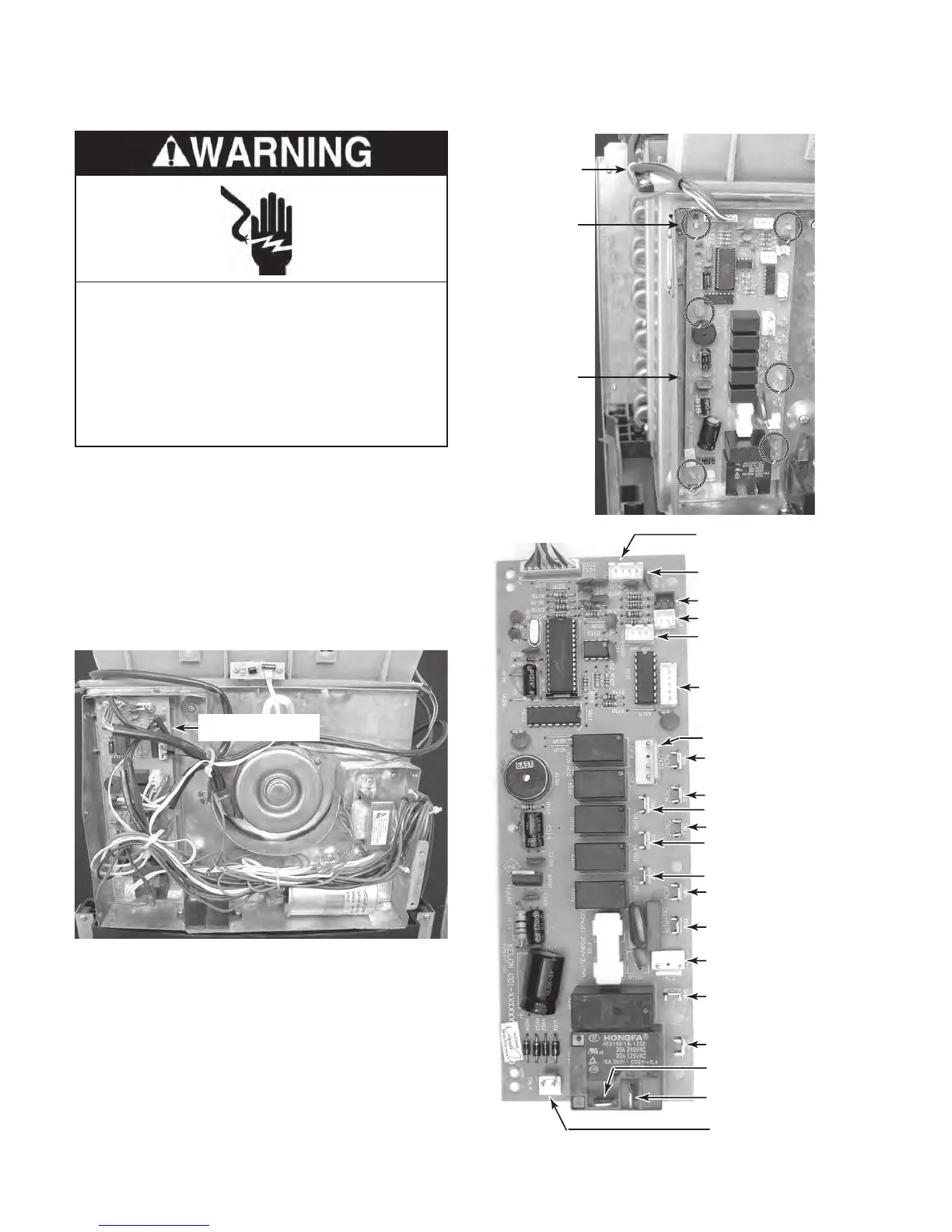
Thermistor (CN1-3 & CN1-4)
hermistor (CN1-1 & CN1-2)
Hi
eceiver Board (CN20)
Louver Motor (CN13
ormer
Wires (CN12)
N/C (CN7)
White
Trans
REMOVING THE CONTROL BOARD
1. Unplug air conditioner or disconnect power.
2. Remove the cabinet from the unit (see
page 4-2 for the procedure).
3.
Remove the components cover (see
page 4-5 for the procedure).
4.
Disconnect the wires from the control
board and its components.
Control Board
5. Cut the wire tie around the user interface
board cable (see the top right photo).
6.
Squeeze the tabs on the ends of the con-
trol board standoffs, and lift the board off
the standoffs.
Wire Tie
Standoff
(1 of 6)
Control
Board
REASSEMBLY NOTE: Be sure to replace the
wire tie that you removed with a new one, and
secure the wires neatly to the chassis.
Electrical Shock Hazard
Disconnect power before servicing.
Replace all parts and panels before
operating.
Failure to do so can result in death or
electrical shock.