4-3
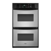
9. To remove the oven control/display
boards:
a) Remove the mounting screws.
b) Lift the ends of the locking arm and
disconnect the ribbon cable from its
connector.
NOTE: The control and display boards are
designed to be replaced as an assembly.
10. To remove the touch panel assembly:
a) Push the window and flat ribbon cable
area out of the control panel so you can
grasp the edge of the touch panel on
the other side.
b) Lift and peel the touch panel assembly
off the front of the control panel.
REASSEMBLY NOTE: When you reinstall the
oven control panel, use the following proce-
dure (refer to the photos on the previous page,
as necessary):
1. Reconnect the wiring to the control board
terminals.
2. Hook the ends of the control panel over
the rubber tips of the brackets.
3. Push the bottom of the control panel in and
position the plastic air duct under the lip of
the panel.
4. Align the mounting holes and install the
two side screws in the control panel.
Bottom Lip Of Control Panel
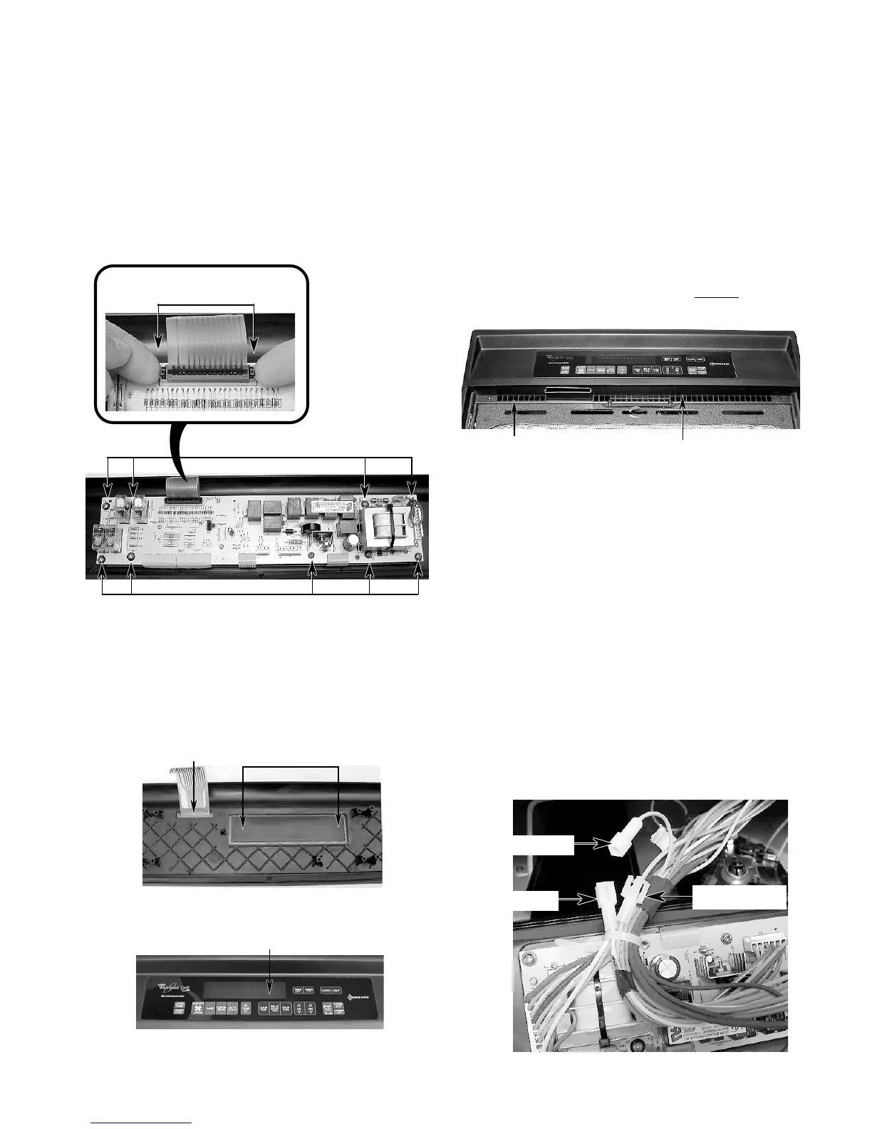
IMPORTANT NOTE: “Cavity size” connectors
(see the photo below) are provided on connec-
tor P3. The connector on the end of the yellow
wire is coming from pin 9, and the connector on
the end of the orange wire is coming from pin
10. This cavity size connector determines the
various cycling of the cooking relays in the 27˝
and 30˝ ovens. Be sure to observe the proper
cavity size configuration for the oven you are
servicing.
24˝ ovens = Open connection
27˝ ovens = Tan wire to Orange wire
30˝ ovens = Tan wire to Yellow wire
Push Out Touch Panel At These 3 Locations
Air Duct
Tan Wire
Yellow (30˝)
Orange (27˝)
Screws
Screws
Lift Ends Of
Locking Arm