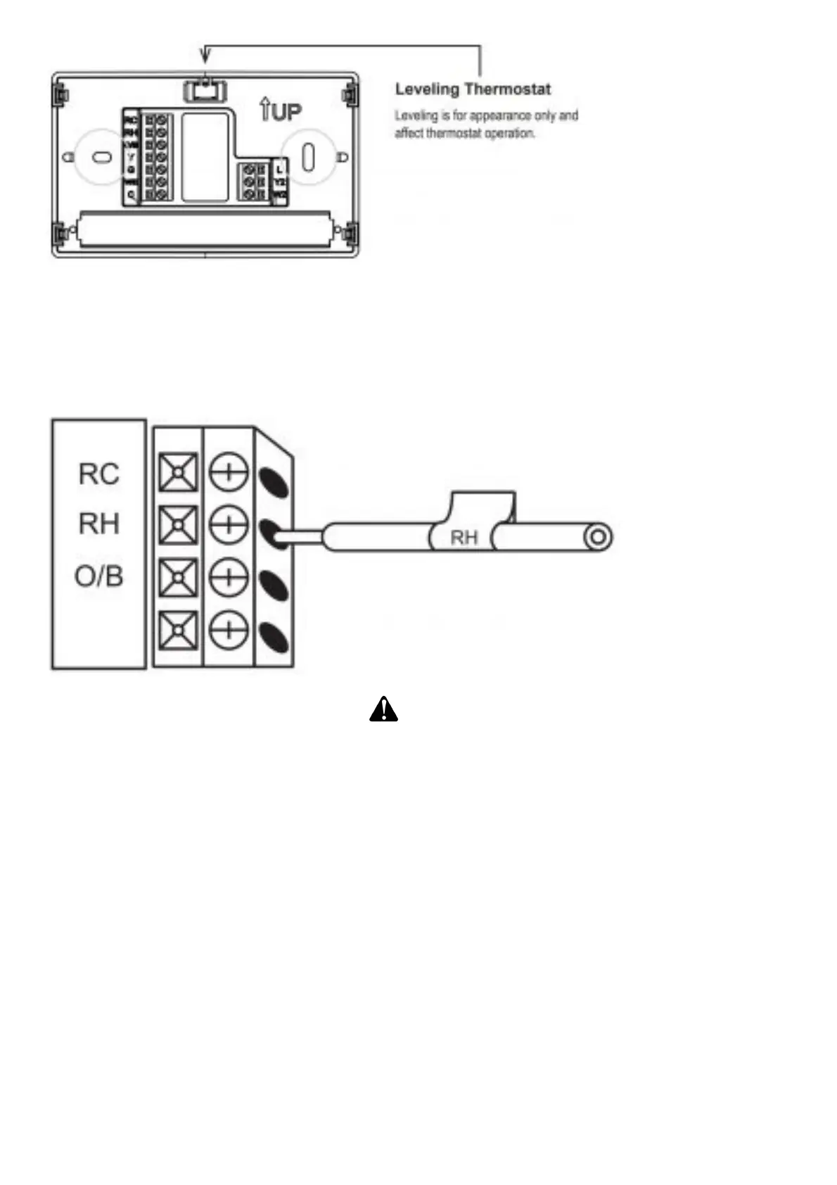
Mount your new thermostat base using the supplied screws. Drill holes and insert wall anchors to
secure the thermostat base to the wall, if necessary.
Connect wires to corresponding terminal blocks
Match each labeled wire to it’s corresponding terminal on the mounted thermostat base. Insert each
labeled wire into the hole of it’s matching terminal, and using the screwdriver, tighten the screw on
the terminal block securely.
CAUTION
Take care when securing and routing wires so they do not short to adjacent terminals or rear of
thermostat. Personal injury and/or property damage may occur.
Identify system configuration
Your wiring can help to determine the type of heating and cooling equipment installed in your home.
Before attaching the front cover, use the following chart, and check the box next to the settings that
match your new thermostat’s wiring. This information will be used in Step 4.5 to configure your
thermostat.
Thermostat Terminals with attached wires: Outdoor Equipment: Setting (Used in 4.5)
No wire on thermostat terminal Y: No air conditioner / no heat pump: AC0
Y (no O/B): Single stage air conditioner: AC1
Y, Y2 (no O/B): Two stage air conditioner: AC2
Y, O/B: Single stage heat pump: HP1
Y, Y2, O/B: Two stage heat pump: HP2
Thermostat Terminals with attached wires: Indoor Equipment: Setting (Used in 4.5)
No wire on thermostat terminal W/E: Blower only (no indoor heating equipment): FAN
W/E (Gas or Oil heat): Single stage gas or oil furnace: GA1
W/E, W2 (Gas or Oil heat): Two stage gas or oil furnace: GA2
W/E (Electric heat): Single stage electric furnace: EL1
W/E, W2 (Electric heat): Two stage electric furnace: EL2