Page 27 2019
WHYTE Service Manual
Then push the Plain Sleeve (2) all the way out of the right side of the Main Frame
(6).
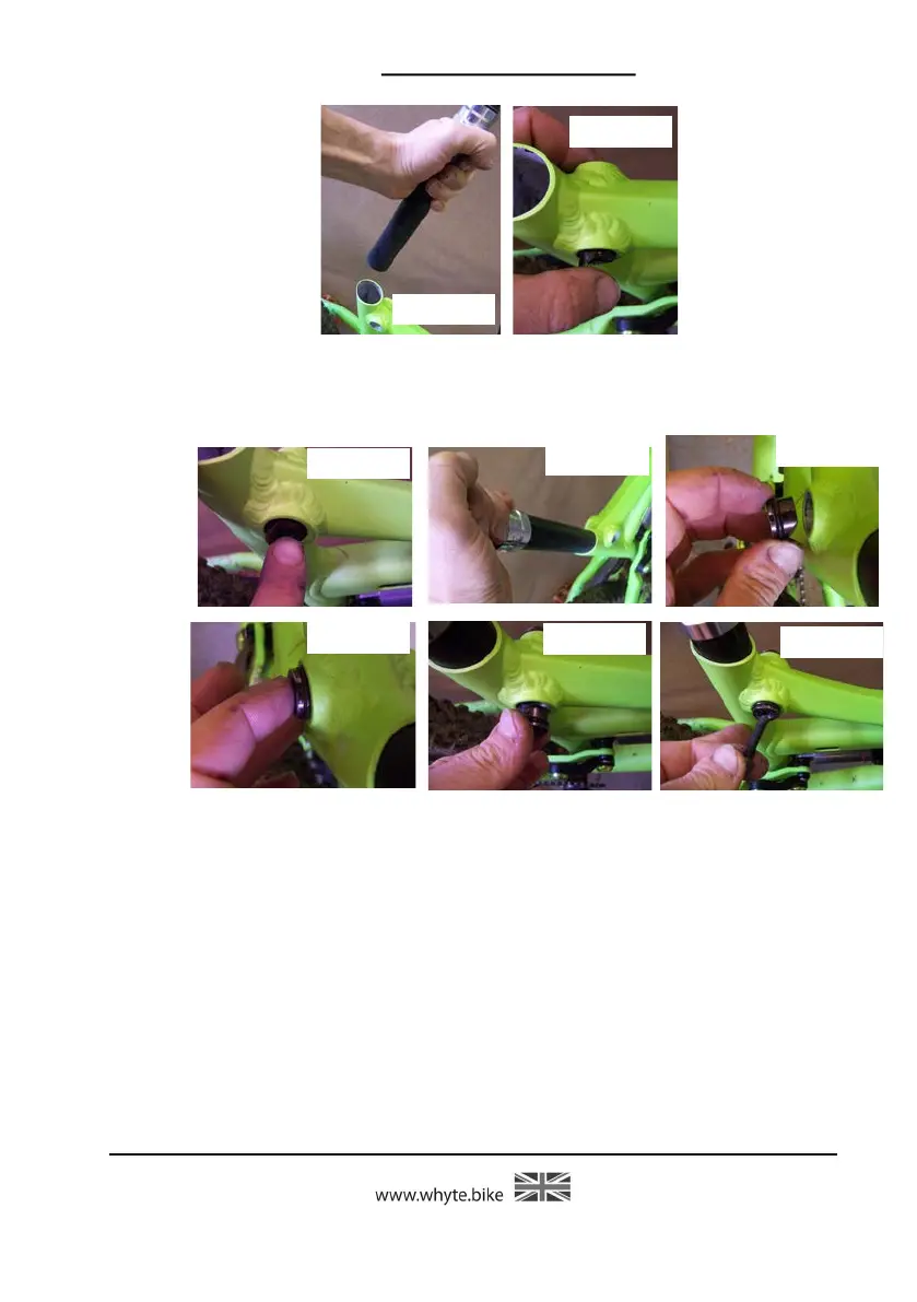
Figures 28 & 29. Remove the Seat Post (7) all the way out of the Main Frame (6).
Remove the Grip Pad (4) from either side of the Main Frame (6). The ‘O’ rings (3)
may be removed from the Threaded Sleeve (5) and the
Plain
Sleeve (2), using the small size flat blade screwdriver.
To re-assemble the Inter Grip seat clamp, coat the ‘O’ rings (3) with a small quanti-
ty of grease. Carefully fit the ‘O’ rings (3) into the grooves in the Threaded Sleeve
(5) and the Plain Sleeve (2). Also place some grease onto the threaded end of the
M6 Capscrew (1).
Figures 30 & 31. Place the Grip Pad (4) into the hole in the Main Frame (6) such
that the curved face is towards the seat tube in the Main Frame (6). Insert the
Seat Post (7) to help align the Grip Pad (4).
Figures 32 & 33. From the left side of the Main Frame (6), insert the Plain Sleeve
(2) and make sure the 45° angled edge on the Plain Sleeve (2) touches the 45°
angled edge on the Pad (4).
Figures 34 & 35. Move to the right side of the Main Frame (6) and insert the
Threaded Sleeve (5), aligning the 45° angled edge to touch the 45° angled edge on
the Grip Pad (4). Place the M6 Capscrew (1) through the Threaded Sleeve (5), the
Figure 30
Figure 31
Figure 32
Figure 33
Figure 34
Figure 35
Figure 28
Figure 29