Installation and operating instructions WILO Mather and Platt – VT pumps 21
4.3 Scope of delivery
Pump can be delivered,
• As a complete pump set including electrical motor, Sole
plate, coupling
• Either without motor or as bare shaft pump without sole
plate in case of existing sole plate and foundation
4.4 Accessories
• Companion Flange
• Foundation
bo
lts
• Shims
5. Product Description
Vertical turbine pump can be single stage or multistage in
construction. The pump is a vertical suction pump.
The unit is divided into three basic elements:
a. The pumping stages including bowl assembly.
b. Intermediate piping works and extension shafting.
c. Delivery bend & motor stool assembly.
The pumping stages are freely suspended from the delivery
bend by intermediate pipework, depending upon the site
conditions. In surface discharge installation, the delivery
bend & motor stool are placed above floor level. The thrust
bearing situated in the motor stool assembly supports the
static weight of the rotating assembly and also absorbs any
axial thrust that is developed within the unit during
operation. (Refer Fig. 10 & 17, Pg. No. 8 & 12) When the
pump is in operation, fluid is guided by a suction cover into
the impeller eye (inlet). Rotation of the impeller vanes
imparts energy to the fluid. This kinetic energy is converted
into pressure energy as the liquid flows through diffuser
vanes.
5.1 Casing
Casing consists of suction bellmouth and diffuser attached
together with impeller and replenishable rings. Casing
carries bush bearings to support shaft at regular intervals.
Depending on need bush bearings can be provided in
suction bellmouth. The top flange surface of casing carries
groove for O-ring for liquid sealing. Also, spigot is provided
on top flange for locating the components accurately.
5.2 Impeller
Impellers may be of mixed flow, Radial flow (open or close).
Refer specifications/datasheet/General arrangement
drawing/cross sectional drawing for details. The impeller
varies in size according to capacity of the individual pump.
Close type impellers are hydraulically balanced to reduce
axial thrust. Impeller carries balance holes and back vane for
thrust balancing. Balance holes can be plugged depending
upon the need. In case of open type of impeller, throat line
is provided below impeller. The gap between the same is
maintained as per pump manufacturer’s recommendations.
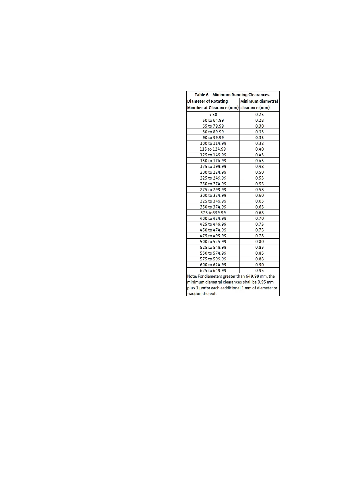
5.3 Impeller wear rings / neck rings
The impellers necks and casing are accurately machined to
provide a close running fit in the neck rings and wear rings that
surround them. The close clearance between the neck ring and
impeller neck as well as wear ring and casing minimizes the
leakage of fluid from the high-pressure areas to the low-
pressure areas of the pump.
Neck rings and Wear rings are renewable to allow this fine
clearance to be restored periodically as wear takes place. Ref.
Table 6 below,
5.4 Rotating Elements
The rotating element consists of the pump shaft, impellers,
intermediate extension shafting and solid muff couplings,
bearing and thrust block.
Impellers are keyed to the pump shaft and located axially. The
complete impeller and pump bearing sleeve assembly is end
tightened against step on the shaft by an impeller lock nut at
suction end. This lock nut is locked in position by locking screw.
Intermediate shafts are coupled together by solid muff
coupling. The weight of the whole rotor assembly is transferred
to bearing via thrust block. Float / lift of the pump can be
adjusted by adjusting thrust block lock nut.
5.5 Rising Main Pipe
Rising main pipes have flanged connections. Spigot joints are
provided in flanges to ensure concentricity. The top rising
column is connected to delivery bend. Grooves for O-rings are
provided for liquid sealing.