Installation and operating instructions WILO Mather and Platt – VT pumps 25
7. Preparing Foundation
The foundation should be sufficiently substantial to absorb
any vibration and to form a permanent, rigid support for the
sole plate. The strength of foundation must be adequate for
the static and dynamic loads imposed and depend upon local
soil conditions. The foundation must get large dimensions.
Generally, the weight of the foundation is around 2 to 3 time
the pump set weight. In building the foundation, the top of
the foundation should be left approximately equal to sole
plate thickness plus 25 mm for packers/shims below, to allow
for grouting. Foundation bolts of the proper size should be
embedded in the concrete, located by template.
Note:
Leave top of foundation rough! Do not finish with trowel.
• A pipe sleeve about 2 ½ diameters large than the bolt should
be used to allow movement for the final positioning of the
bolts. For installations where a low level of noise is expected,
built the foundation in a pit lined with appropriate insulation
material in order to avoid vibration transmission to the
ground.
CAUTION! Risk of material damage!
While tightening pump screws/bolts, pump as well motor
should be free and should not be in coupled condition.
Pump or motor should not be used as supports while
tightening.
• Ensure that both Sole plate faces are parallel within
allowable value, free from any distortion as shown in fig.
Spirit level, straight edge along with engineer’s mater level
can be used to check flatness.
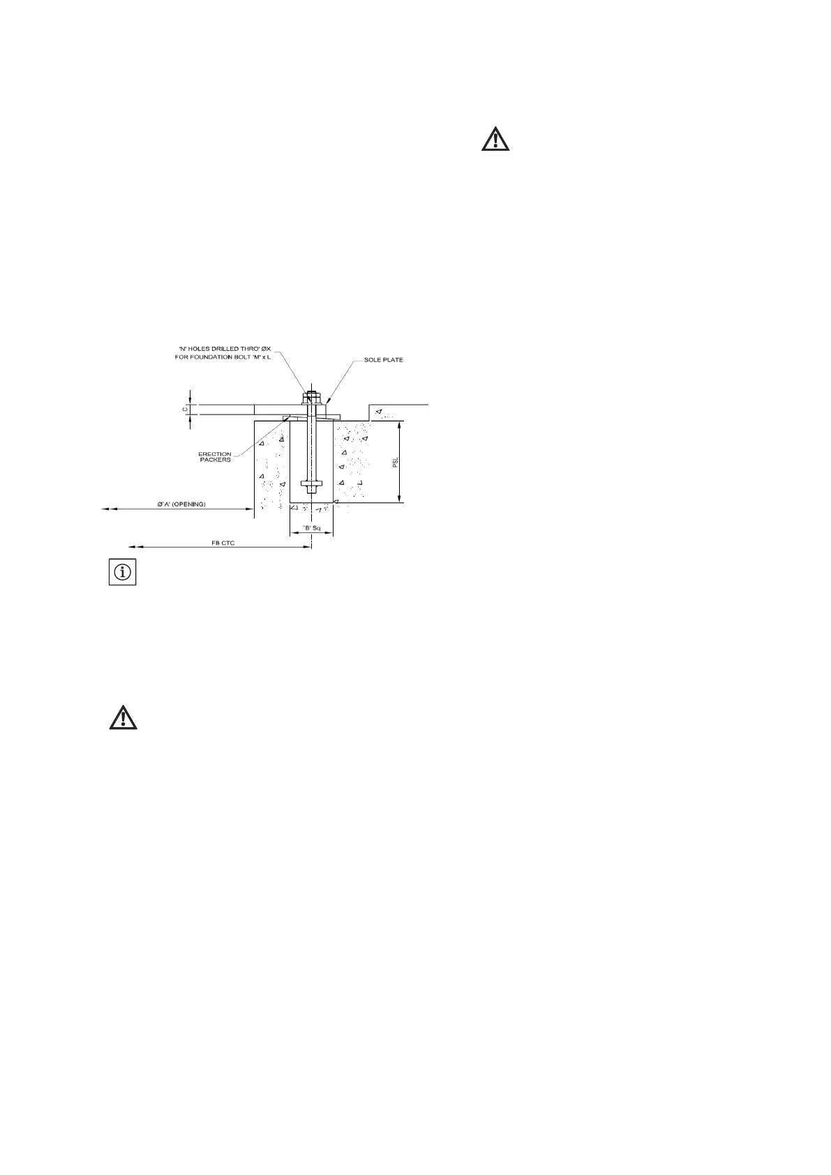
7.1 Sole Plate Installation
Sole plate has machined surfaces on both top and bottom
sides. The top surface of foundation over which the sole
plate rests must be left rough to assist in keying the final
grout. After the sole has been leveled by positioning steel
packer plates at suitable intervals on the foundation surface,
ensure that the surface beneath each packing plate is solid
by crushing any protrusion or alternatively each packer plate
may be placed on a thin screen of cement.
7.2 Levelling of Sole Plate (Fig: 7, Pg. No. 7)
CAUTION!
The machined surfaces where level is being checked
must be clean and free from paint, burrs etc.
Provide suitable packer plate (25 mm to 30 mm thick) or
taper wedges on the foundation one each of either side
of foundation bolt and in-between around 250 mm
center to center. It is advisable to provide thin layer of
cement below the packer plate.
• Lift the soleplate and lower it on the foundation. Insert
the foundation bolts through the holes in the soleplate
and screw a nut on to each bolt until the bolt protrudes
through the nut by a length, which is sufficient to
accommodate a lock nut.
• Adjust the level of the soleplate by inserting shims
between the soleplate and the packer plate until the
soleplate is leveled. And support on all the packing
wedges at suitable height. For checking the levels &
straightness, I-beam type straight edge should be used
extensively in conjunctions with engineer’s master level.
Level should be achieved within 0.02 mm per meter. Also
ensure that elevation of bedplate is adjusted suitably.
• For grouting use rich mix of 1:1:2 of cement, sand and
gravel below 12 mm, alternatively quick setting grout mix
can be used.
• When the grout has set, gently but firmly tighten the
foundation bolts. Do not to distort the soleplate or loosen
the foundation bolts in the grout by excessive tightening.
Carefully re-check the level of the soleplate and make
adjustments that are necessary by fine shimming. Ensure
that the sole plate is leveled, as per the site datum level,
various centerlines etc. (Refer Fig: 7 Pg. No. 7)