Installation and operating instructions WILO Mather and Platt – VT pumps 37
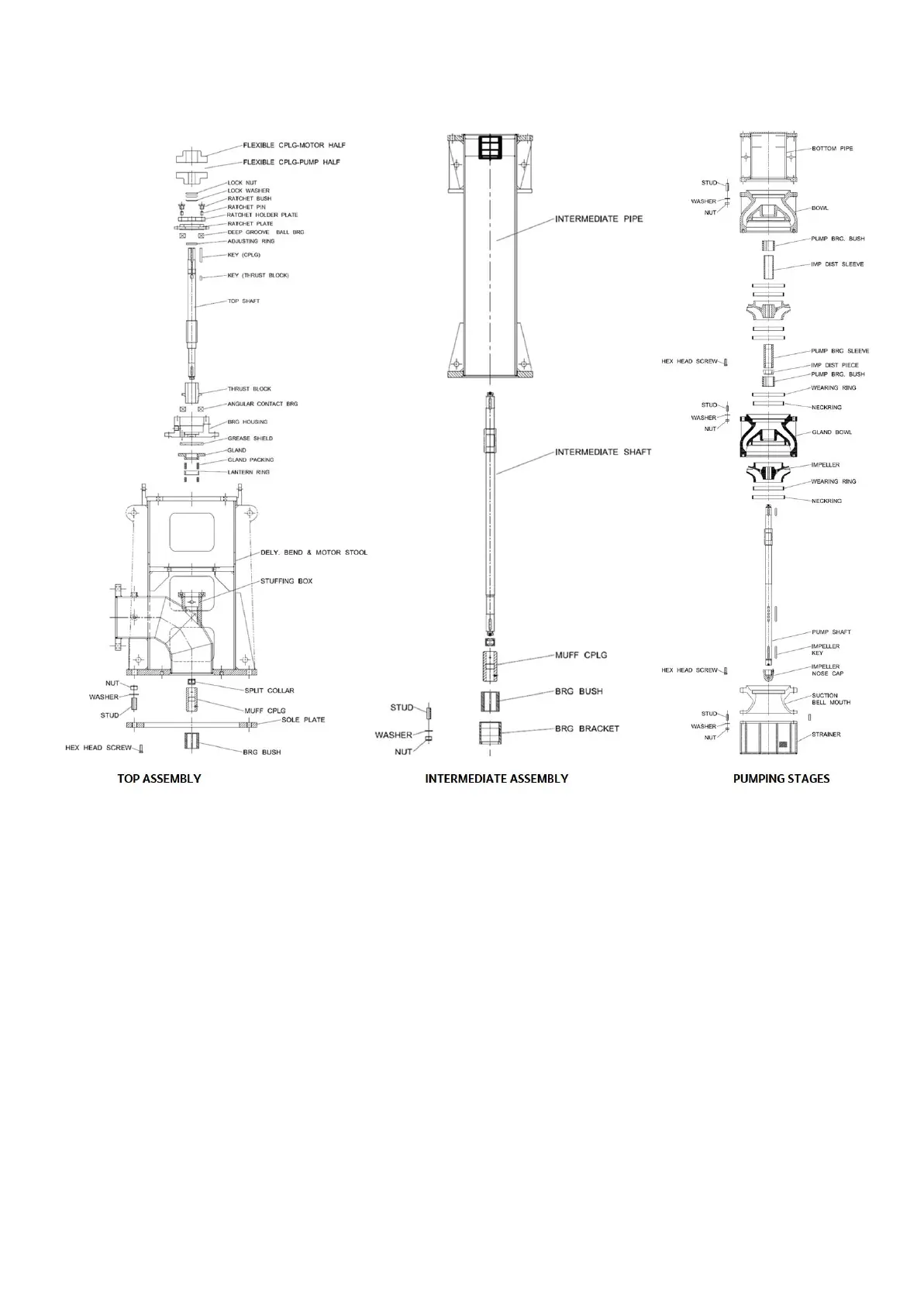
11.3 Disassembling the Pump
11.3.1 Disassembling the top Motor
• Isolate the pump motor electrically
• Isolate the pump system hydraulically
• Clear the area of any equipment that might impede the
free lifting of the pump
• Disconnect the electrical supply cables from the motor
terminal block
• Disconnect and remove the driver couplings.
• Attach slings and lifting apparatus to the motor lifting
attachments
• Remove the screws / bolts, or nuts, from the motor
flange and lift the motor off the combined delivery bend
& motor stool. Support the motor on timber packing
blocks with the coupling hub clear off the ground
11.3.2 Disassembling of top and intermediate
assembly
• Remove the pump coupling, spacer, key and dismantle
the coupling assembly
• Remove lock nut lock screw to bring the rotor lift in
downward position.
• Remove ratchet plate holder, rachet pin, ratchet bush and
remove the ratchet plate
• Drain the oil (if applicable) from bearing housing and remove
bearing housing cover and gasket
• Remove cooling coil (if applicable) and the connections
• Remove the bearings, thrust block and bearing housing and
the oil retainer bush
• Remove gland, gland packings / mechanical seal, leak valve
and pipeline
• Remove motor stool and top shaft along with muff coupling
and split collar, shaft key and the grub screw
• Remove the rising main pipe (top) / discharge bend column
pipe and rest the entire rotor assembly on C clamps.
• Remove the rising main pipe (int.) one by one along with
Intermediate shaft, intermediate bearing assembly, split
collar, muff coupling, grub screw until arrival of bottom rising
main pipe bottom
• Again, lift the rest of pump assembly and till the next column
pipe rests on beams. Follow the same steps till pump casing
level is reached.