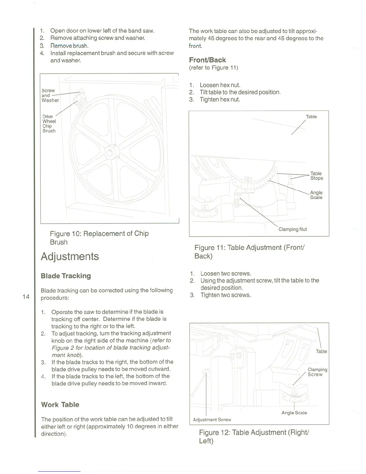
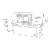
1. Open door on lower left of the band saw.
2. Removeattachingscrewandwasher.
3. Removebrush.
4. Install replacementbrushand securewith screw
andwasher.
<I
I,
I /,/
~~~
.
1f
.
~;;fr,~
.
Drive
\
Iii ( I If II!
~~" :1~~~ I\~/'<~\I
"I(~~'2I~~?" I
lil",\,
.
"'1\ ~1@0~ '
>
~~~~~~ )
.
11
\\\\j/' // \ \~ "~j!i
\\\~;:/-\\ \1 ~. ///,
I'I\
'I\"
~
\\:
I
I
\
1 )$
\
\1, I, 4
'I I, ~\<lII';\\j!
"
\
\ ~ ~----------
,/
[--------.---------------I
Figure 10: Replacement of Chip
Brush
Adjustments
Blade Tracking
14
Blade tracking can be corrected using the following
procedure:
1. Operate the saw to determine if the blade is
tracking off center. Determine if the blade is
tracking to the right or to the left.
2. Toadjust tracking,turnthe tracking adjustment
knob on the right side of the machine (refer to
Figure 2 for location of blade tracking adjust-
ment knob).
3. Ifthe bladetracks to the right, the bottom of the
blade drive pulleyneedsto be movedoutward.
4. Ifthe bladetracks to the left, the bottom of the
blade drive pulley needsto be moved inward.
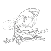
Work Table
The positionof the work table can beadjustedto tilt
either left or right (approximately 10 degrees in either
direction).
The work table can also be adjusted to tilt approxi-
mately 45 degrees to the rear and 45 degrees to the
front.
Front/Back
(referto Figure11)
I
1-
1. Loosenhexnut.
2. Tilt table to the desired position.
3. Tightenhex nut.
Table
~ - /
~7----
\'0~\\\.~ -/------
..j -~ 0 I" Table
~~!'Pi!\!f:! ,~s""
r
I ~r \ I,
I
\
~Angle
''I \ \ Scale
1 ~~
~
~)L-J
!~~
.
~ I r- 'I /
\
"'
P
~L---~) -- / \
'" rJi', A
Oj
\
\
'I "
~~~/
o
I, i'
,,° I'TI", 'i I, ' ~
\..-!'-~".../I 1
Clamping Nut
Figure 11:Table Adjustment (Front!
Back)
1. Loosentwo screws.
2. Usingthe adjustmentscrew,tilt thetable to the
desired position.
3. Tightentwo screws.
.. ~ -..
~3~~-S;::>- "
::: / ,_,:::F>-. 'S::
.
:
.
-~ 'I I
,-/,/_:
.
--.
. '-, /, ,.1 ..//./1'
I
.
1 /1
j
rl ~-
J
' ~--~~":::::cc- :;
\
.
~ ,= - - I '-. '
., I.!/ Iii ",-- / ."i ii'> ,
"!:/~1~~1..,/1 !l:~"
I
I
,
.
1
I
I
.
-:{ /
;?(
Clamping
1 ' Screw
I
I
'I~\
=:. t- I J, - - -r,;,iD>l
I rFi:I~UII :(L~~~\
Angle Scale
Adjustment Screw
Figure 12: Table Adjustment (Right!
Left)